The key appears in the I/O menu only when at last one of the previous auxiliary I/Os is present.
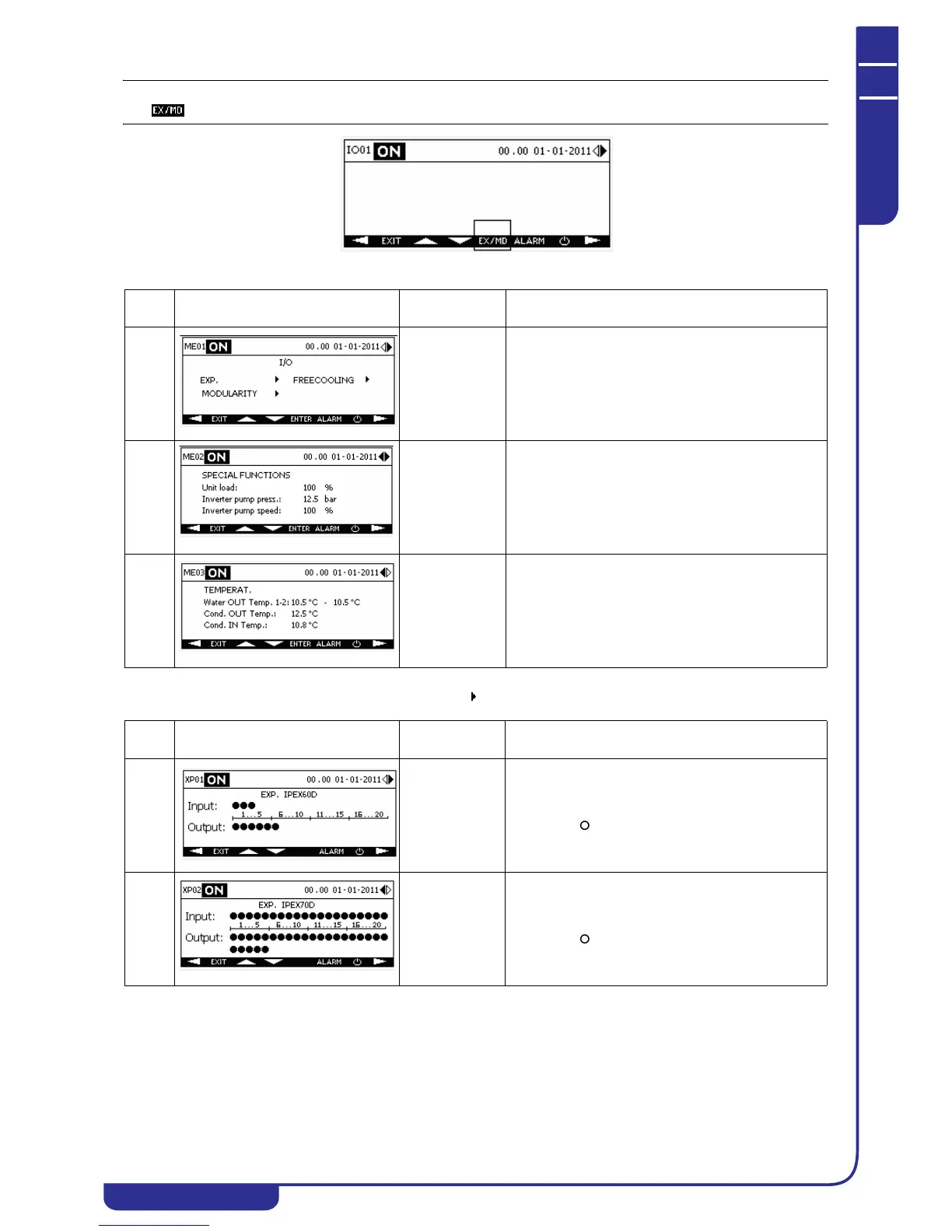
The XP menu is accessible from the ME menu, selecting the icon corresponding to the expansions (EXP) in mask ME01.
Ref. Mask
Display
conditions
Description
ME01 With expansion
modules present
or modularity /
free-cooling
enabled
Provides the facility to access the menu for display of
digital I/Os of the expansions, information concerning
slave modules of a modular system (see dedicated
xCONNECT manual) and free-cooling. The mask
contains the options exclusively of the functions
enabled on the unit.
ME02 With special
machine loading
functions or
inverter pump
functions
enabled
Displays the percentage of the machine load, if
enabled.
Displays pressure value and speed percentage of the
inverter pump if enabled.
ME03 With evaporator
water outlet dual
probe or
condenser probes
enabled
If the unit is equipped with two evaporator water
outlet probes, displays the temperature values. The
average value is shown in the main menu.
Displays the temperature values of the condenser
water inlet and outlet probes if present on the unit.
Ref. Mask
Display
conditions
Description
XP01 On units with
expansion
module
IPEX60D (IPX
106D) present
Displays the status of digital inputs and outputs of
expansion module IPEX60D (IPX 106D) if present on
the unit. The icon denotes a digital signal at logical
level 1, the icon at logical level 0.
XP02 On units with
expansion
module
IPEX70D (IPX
125D) present
Displays the status of digital inputs and outputs of
expansion module IPEX70D (IPX 125D) if present on
the unit. The icon denotes a digital signal at logical
level 1, the icon at logical level 0.