MAINTENANCE AND OPERATING MANUAL
Electronic controller
HAS T 070÷140
69
ENGLISH
EN
The data in this manual are not binding and they can be modified by the manufacturer without notice. Reproduction of this manual is strictly prohibited.
In control by temperature it is possible to select the reference probe from between:
• BRWOT (if present)
• BRWIT (if present)
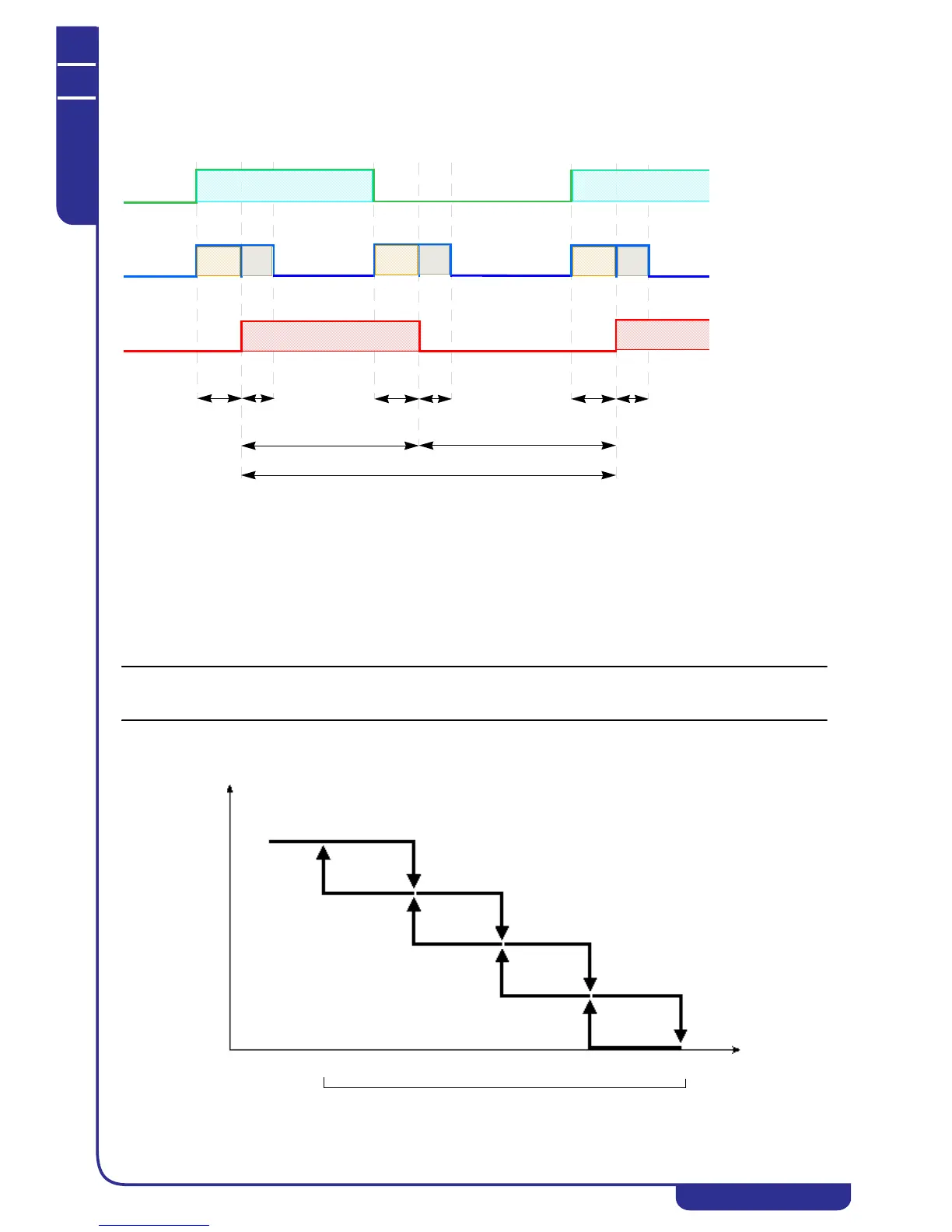
6.7.7.2Recovery operating logic
The heat recovery activation logic on a circuit is illustrated in the following diagram:
By-pass activation means capacity control of the circuit during recovery activation and deactivation stages. Capacity control
occurs with stopping of a compressor in the circuit. The duration of capacity control is imposed by the sum of times T1+T2
(see diagram).
Specifically:
T1 = recovery activation time lag
T2= by-pass deactivation time lag
Activation of heat recovery means opening of the solenoid valve to transfer the flow of superheated refrigerant from the
condenser to the recovery exchanger.
Heat recovery complies with the minimum On and Off times and the interval between consecutive recovery procedures set on
the display.
During heat recovery the fans of the circuit in question are switched off. If two circuits share the same row of fans, the fans
are switched off only if heat recovery is in progress on both the circuits in question.
The recovery request can be managed in relation to the temperature detected by the probe located on the heat recovery
exchangers. This mode can be activated only in the presence of "Total" or "Partial single" recovery. The following diagram
describes the control logic of a machine with 4 recovery exchangers: