MAINTENANCE AND OPERATING MANUAL
Electronic controller
HAS T 070÷140
71
ENGLISH
EN
The data in this manual are not binding and they can be modified by the manufacturer without notice. Reproduction of this manual is strictly prohibited.
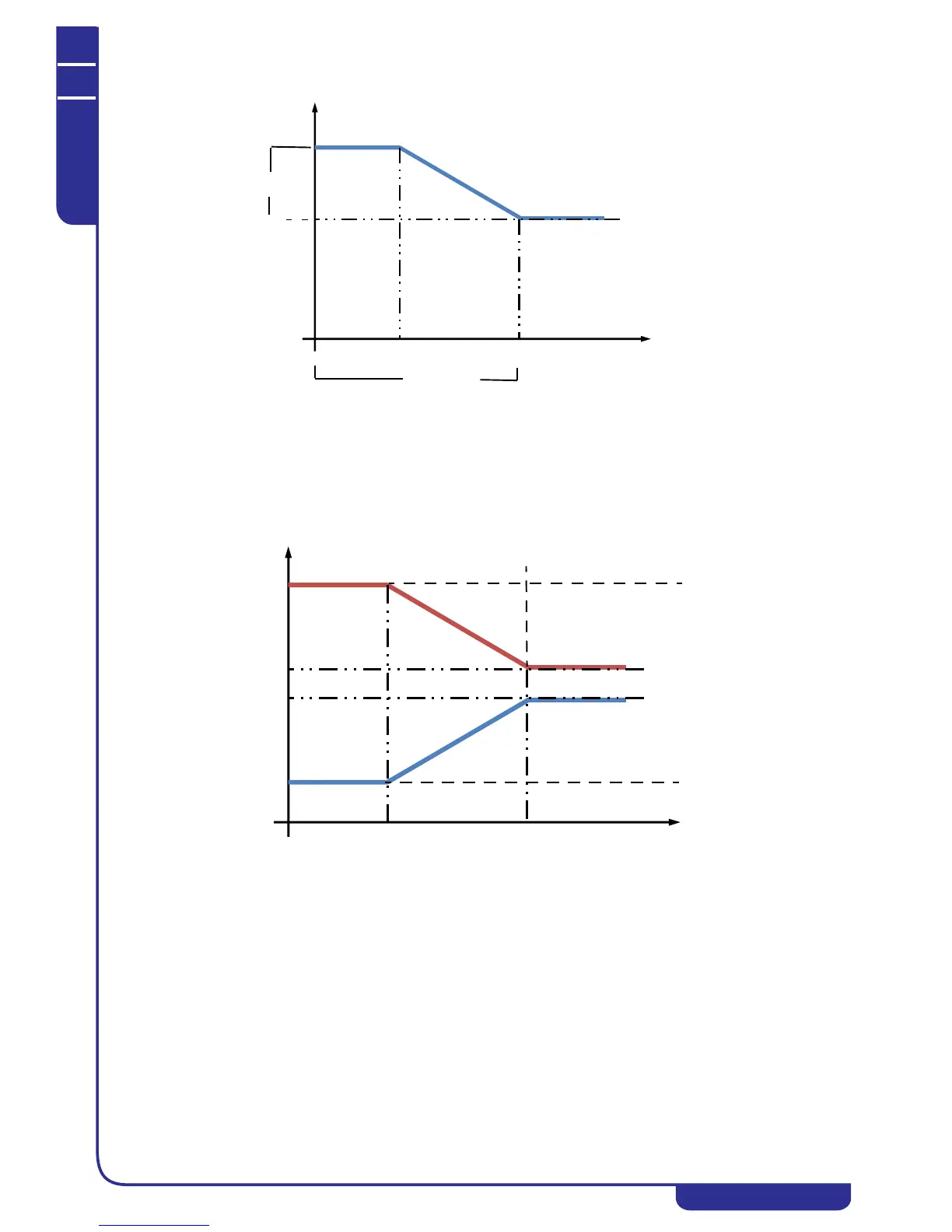
If a negative compensation differential is defined, the compensated setpoint diagram is as follows:
SETPOINT BY TIME BAND
• You can define four different time bands, each of which corresponding to a fixed setpoint. When the current
time is within a time band, the corresponding setpoint is applied. The ending time of each hourly time band
corresponds to the starting time of the next band.
ADJUSTABLE SETPOINT
• The setpoint is variable and it is calculated in accordance with an analog input signal of the 4...20 mA type, in
accordance with the following diagram:
In chiller mode, the chiller fixed setpoint corresponds to a 4mA input signal, while the maximum chiller setpoint, editable
from the display, corresponds to a 20mA input signal.
In heat pump mode, the heat pump fixed setpoint corresponds to a 4mA input signal, while a 20mA input signal corresponds
to the maximum heat pump setpoint editable on the display.
6.7.8.2Regulation types (PID - neutral zone)
There are two regulation types settable on the display:
•PID
• Neutral zone
PD REGULATION
In PID regulation the reference temperature is controlled by means of a proportional + integral + derivative action in
accordance with PID regulation logic. Regulation therefore depends on the contribution of three parameters:
KP: proportional coefficient. This is the value of the regulation band, i.e. the deviation with respect to the setpoint.
Increasing this value reduces the error at steady state operation, but it makes the system less stable;
KI: integral coefficient. This is the time in which the temperature remains stable. The contribution of this coefficient cancels
the error at steady state conditions but tends to make the system less stable (Re. RG04);