OPERATING AND MAINTENANCE MANUAL
Chapter 10 - Troubleshooting
TAEevo Tech 015÷802 60 Hz UL
190
The data in this manual are not binding and they can be modified by the manufacturer without notice. Reproduction of this manual is strictly prohibited
ENGLISH
EN
C
The level sensor and/or
flow meter alarm FLOW
trips.
Alarm displayed:
AEFL
C1
Unit upline filter, if
present, is clogged.
C1.1
• Water flow is irregular.
Pressure difference between
inlet and outlet below 25mbar /
0.36 PSI;
• The text AEFL appears on the
display;
• General alarm relay activation.
Clean the filter upline from the
unit, if installed.
Perform the alarm reset
procedure to restart the unit (see
Electronic controller).
C2
The pump does not work
or rotates in the opposite
direction (three-phase
power supply).
C2.1
• See C1.1;
• General alarm relay activation.
Check the pump electrical
supply and, if necessary, invert
two of the phases.
Perform the alarm reset
procedure to restart the unit (see
Electronic controller).
C3
Water inlet-outlet
inverted (units without
hydraulic kit).
C3.1
• See C1.1;
• General alarm relay activation.
Invert water inlet and outlet.
Perform the alarm reset
procedure to restart the unit (see
Electronic controller).
C4
The storage tank has not
been bled correctly.
C4.1
• The text AEFL appears on the
display;
• General alarm relay activation.
Bleed the storage tank via the
relative bleed valve.
D
High pressure switch (HP)
trip
(TAEevo Tech 015÷401
models only)
Alarm displayed:
b(n)HP
D1
The fan doesn’t work.
D1.1
• Refrigerant compressor stops;
• The text b(n)HP appears on
the display alternating with
value of BTOWT;
• General alarm relay activation;
Repair or replace the fan.
Where fitted, check the circuit
breaker of the fan.
Perform the alarm reset
procedure to restart the unit (see
Electronic controller).
D2
Ambient air temperature
too high.
D2.1
• Ambient air temperature
higher than maximum
permitted value;
• See D1.1.
If the unit is installed in an
enclosed place, reduce ambient
temperature to within the
prescribed limits, for example
by increasing room ventilation.
Perform the alarm reset
procedure to restart the unit (see
Electronic controller).
D3
Recirculation of warm air
due to incorrect
installation.
D3.1
• Condenser cooling air
temperature higher than
maximum permitted value;
• See D1.1.
Change the position of the unit
or the position of any nearby
obstructions in order to prevent
recirculation.
Perform the alarm reset
procedure to restart the unit (see
Electronic controller).
D4
See A3.
D4.1
See D1.1.
Clean the condenser fins.
Perform the alarm reset
procedure to restart the unit (see
Electronic controller).
D5
See A4.
D5.1
See D1.1.
Remove the obstruction from
the front surface of the
compressor.
Perform the alarm reset
procedure to restart the unit (see
Electronic controller).
D6
Thermal load too high.
D6.1
• Water outlet temperature too
high;
• Refrigerant compressor stops;
• General alarm relay activation.
Restore thermal load to within
prescribed limits if possible.
Perform the alarm reset
procedure to restart the unit (see
Electronic controller).
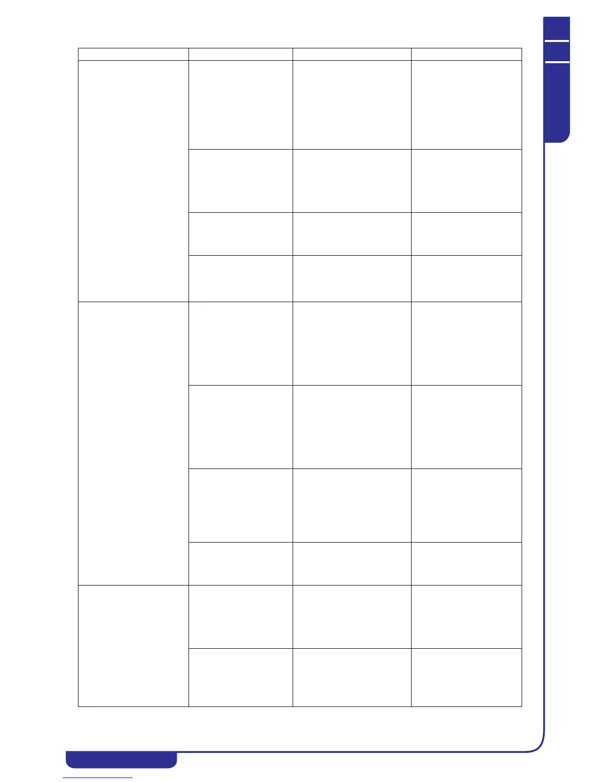
PROBLEM CAUSE SYMPTOM REMEDY