With this procedure you can reset all the alarms except for the compressor thermal cut-out alarms for which the
password will be required: 14.
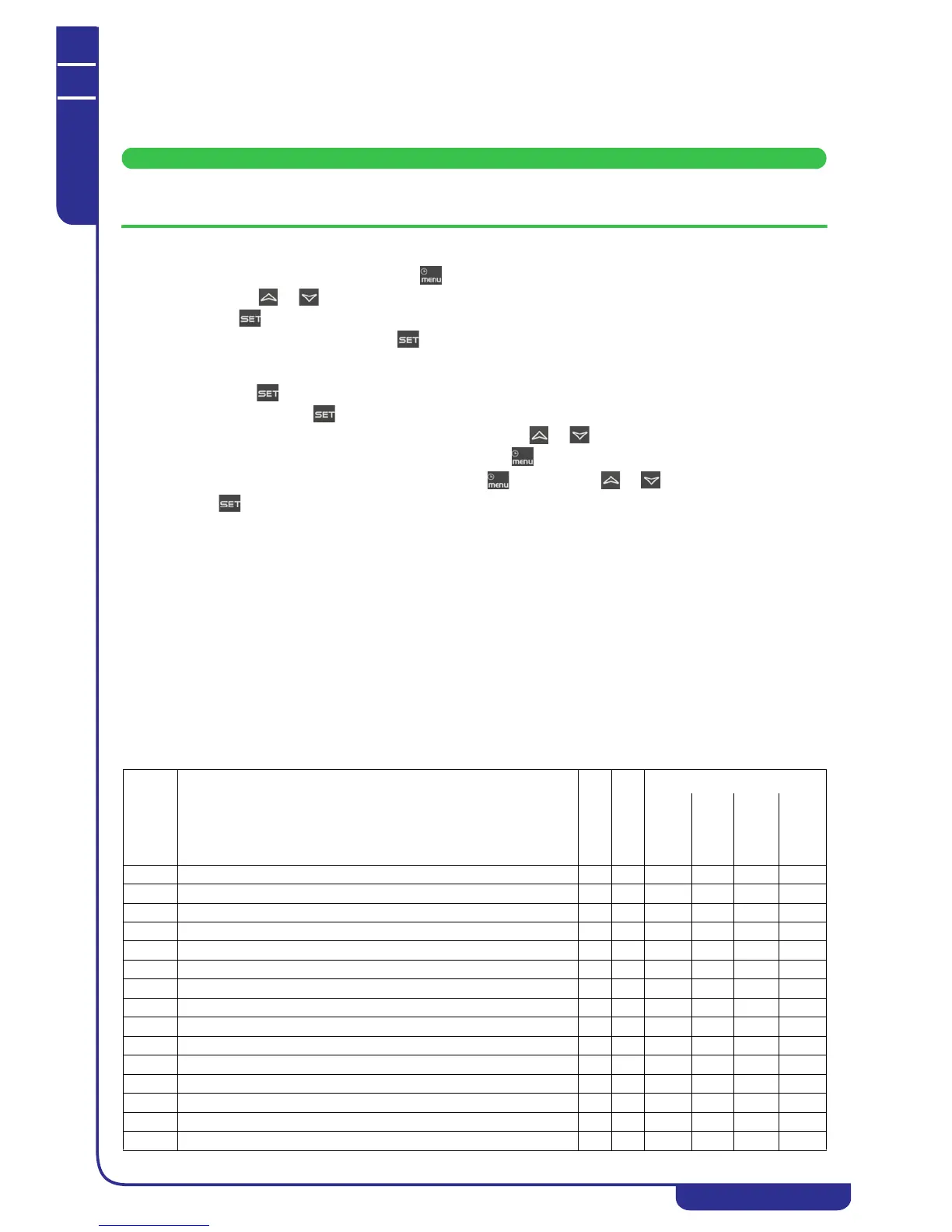
To open the functions menu proceed as follows:
• Open the functions menu by pressing
• With the or buttons select the ALrM function
•Press .
If no alarms are present, pressing is not enabled.
• The lower display shows the label with the alarm; the upper display, if the alarm displayed is resettable, shows
the label rSt or no if the alarm condition is still present.
• Pressing in correspondence with label rSt resets the alarm and the system goes to the next one; if this too
is resettable, press to reset it and go to the next one.
• If you want to scroll through all the alarms present press or .
To exit the ALrM function and return to normal display mode press or wait for the time-out.
With the unit in StbY (stand-by) and the LED flashing, press and scroll with or to select the ALrM function
and press button to display the active alarm.
7.11.2 How to mute the buzzer
The controller emits an audible signal to alert the operator to the presence of alarms (buzzer).
The buzzer is muted in the following ways:
• Automatic muting: the buzzer is muted when the situation that caused the alarm ceases.
• Manual muting: press and release one of the buttons; the buzzer will be muted even if the alarm condition
persists.
7.11.3 General alarms list
Alarm codes and indications are composed of letters and numbers that identify different alarm types.
The first letter of the alarm label identifies the type as follows:
•Letter A = unit alarm
•Letter b = circuit alarm
•Letter C = compressor alarm
The following tables contain a description of the alarms managed by the electronic circuit board. Some of the alarms
mentioned may not be referable to all unit models.
Outputs block
COD.
alarm
Alarm
Description
Alarm reset
Alarm Trip
Compressor
Pump
Fan
Heaters
AP1 Probe PB1 fault alarm A I X X X(1)
AP2 Probe PB2 fault alarm A I X X X(1)
AP3 Probe PB3 fault alarm A I X X X(1)
AP4 Probe PB4 fault alarm A I X X X(1)
AP5 Probe PB5 fault alarm A I X X X(1)
AP6 Probe PB6 fault alarm A I X X X(1)
APE1 Probe PB1.. Probe Pb8 of I/O expansion A I X X X
APE2 Probe PB1.. Probe Pb8 of I/O expansion A I X X X
APE3 Probe PB1.. Probe Pb8 of I/O expansion A I X X X
APE4 Probe PB1.. Probe Pb8 of I/O expansion A I X X X
APE5 Probe PB1.. Probe Pb8 of I/O expansion A I X X X
APE6 Probe PB1.. Probe Pb8 of I/O expansion A I X X X
APE7 Probe PB1.. Probe Pb8 of I/O expansion A I X X X
APE8 Probe PB1.. Probe Pb8 of I/O expansion A I X X X
AEFL Level sensor and/or flow meter alarm A/M R X X(2) X X