OPERATING AND MAINTENANCE MANUAL
Chapter 5 - Installation
TAEevo Tech 015÷802 60 Hz UL
29
The data in this manual are not binding and they can be modified by the manufacturer without notice. Reproduction of this manual is strictly prohibited
EN
ENGLISH
For mains power input:
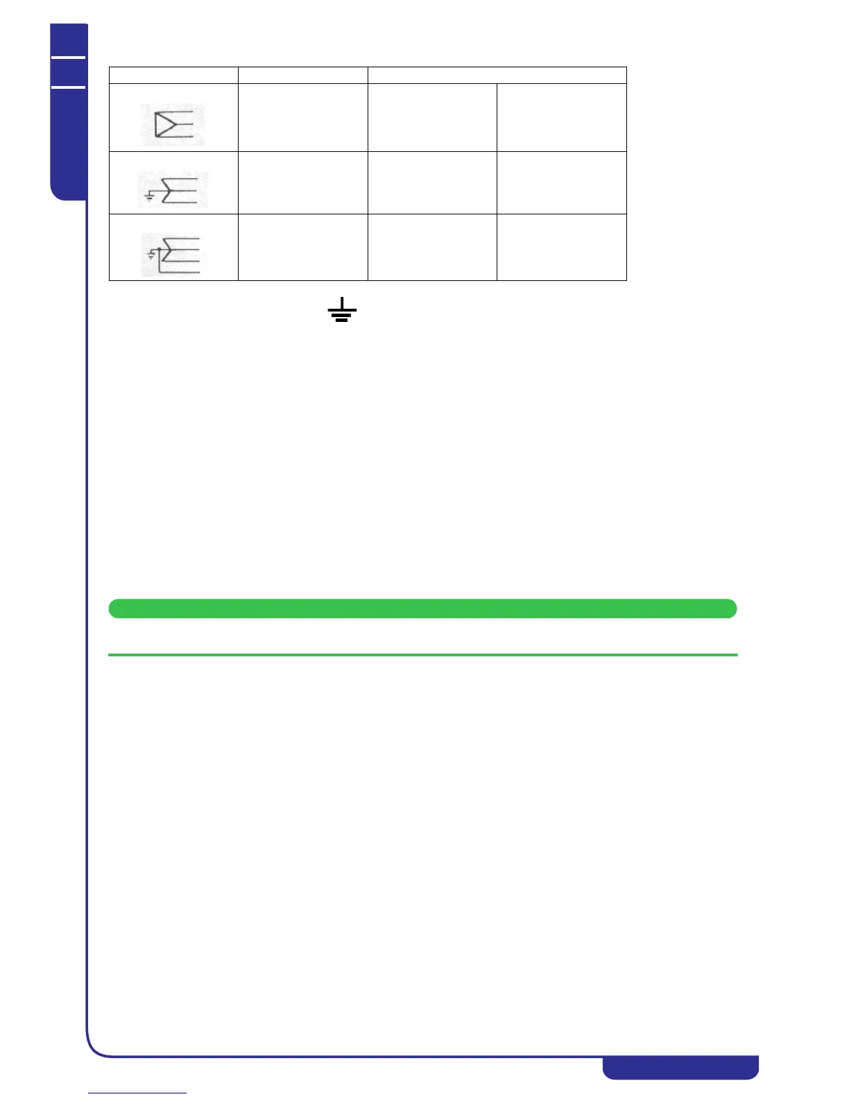
1. Connect the machine (terminal in the electrical panel) to the earth system of the building;
2. Provide protection against direct contact of at least NEMA Type 1 upline from the power cable;
3. Fit a device protecting the power cable from overcurrent (short-circuit) (see indication in the electrical diagram)
upline from the power cable. For this purpose, all protection devices must be homologated (“listed”).
4. Use conductors which can carry the maximum current required at the maximum ambient operating temperature,
according to the type of installation chosen (seeindication in the electrical diagram). Use only UL marked copper
cables, in conformity with NEC (NATIONAL ELECTRICAL CODE) and CEC (CANADIAN ELECTRICAL
CODE).
5. After the connection to the circuit breaker/switch (as indicated in the wiring diagram), the unit’s power cable must
exit the unit by the appropriate hole positioned on the back panel and identified by a label with the indication of
the power supply.
5.7 Phase Monitor
By means of a Phase Monitor device (see unit electrical schematic) the electronic controller is able to monitor the unit’s
power supply, stopping the unit in the case of missing phases or an incorrect phase sequence.
Tripping of the Phase Monitor shuts down the unit and displays alarm ALc1.
A certain level of power supply instability is perfectly normal. If the frequency with which the unit is shut down due to
tripping of the Phase Monitor tends to increase unacceptably, contact your local electricity company to find a solution.