6.1 SYSTEM SETUP (CONTINUED)
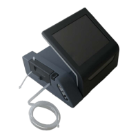
6.1.6 Insert the tubing cassette into the side of the console.
6.1.6.1 Ensure that the tubing in the semi-circular cutout of the cassette mates with the
peristaltic pump head.
6.1.6.2 Press the cassette straight down firmly until it locks in place.
6.1.7 Hang the irrigation solution bottle/bag (not included) on the IV pole hanger.
6.1.8 Close the roller clamp on an administration tubing set (not included).
6.1.8.1 Roll the clamp roller until the tubing is collapsed to prevent fluid flow through tubing.
6.1.9 Insert the drip chamber spike into an irrigation solution bottle/bag (not included).
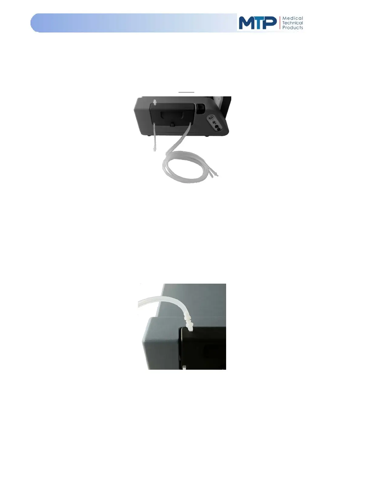
6.1.10 Connect the administration tubing set (male fitting) to the cassette administration tube
(female fitting).
6.1.10.1 Prime administration tubing set by squeezing drip chamber.
6.1.11 Hang the collection bag from the hanger located on the bottom center of the cassette.
6.1.12 Connect the collection tube from the cassette to the collection bag.
6.1.13 Power ON the system by pressing the power switch on the back panel to the “I” ON
position.
6.1.14 Calibrate Foot Pedal (See Section 5.9.17 Foot Pedal Calibration Procedure)