“Confidential, Do Not Duplicate without written authorization from NEC.”
8-12
CIRCUIT DESCRIPTION
2. Circuit operation
1 Connector M9501
1) Input terminal
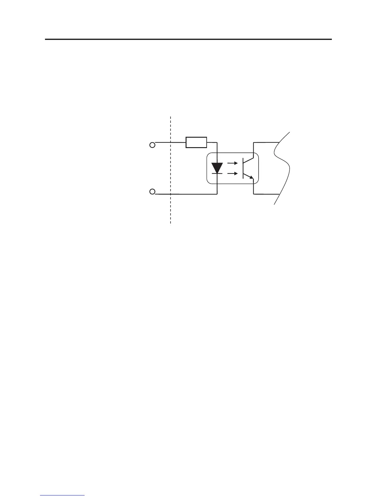
These connector pins specified below are used as the input pins. They are connected to the photo coupler on
the PWB.
• Input Pin 1 ~ Pin 8 (anodes of the photo coupler): Ext_GPIO_P
• Input Pin 20 ~ Pin 27 (cathodes of the photo coupler): Ext_GPIO_N
Photo coupler
Voltage in forward direction: 1.1V (@5mA)
Recommended operating current: 5mA
Absolute max. rating: 50mA
Resistance =390Ω
Projector interior
Ext_GPIN_P
Ext_GPIN_N
GPI/O terminal
Pin No. : 1 2 3 4 5 6 7 8
Pin No. : 20 21 22 23 24 25 26 27
As described above, there are circuits connected with the diodes of Photo Coupler IC9501 ~ IC9508 between
Ext_GPIN_P and Ext_GPIN_N. There are eight such circuits available in all.
When a voltage is applied between Ext_GPIN_P and Ext_GPIN_N, the photo coupler diode can be turned
ON and OFF.
Usually, Connector M9501 is in OPEN state. Therefore, the photo coupler remains to be turned OFF.
The voltage to be applied between Ext_GPIN_P and Ext_GPIN_N to get the photo coupler turned ON should
be kept between DC 3.3V and DC 10V. If this voltage is lower than DC 3.3V, the photo coupler cannot be
turned ON, thus failing in operation. If a voltage higher than DC 10V is applied, the photo coupler can be
destroyed. This voltage should be maintained at a positive potential (+) on the Ext_GPIN_P side (Pin 1 ~ Pin
8 side) and at a negative potential (—) on the Ext_GPIN_N side (Pin 20 ~ Pin 27 side). A resistor of 390Ω is
inserted in series on the photo coupler diode side.
When a current of 5mA is carried through this diode, the forward voltage of the diode becomes 1.1V.
The signal input entered from this circuit is picked up from the collector of the output side transistor in the
photo coupler. This signal input is divided into two portions. One is led to the Cinema System circuit
(INTERFACE Board) through Connector PO6005 and the other is applied to the CPU PWB via the POCO.