“Confidential, Do Not Duplicate without written authorization from NEC.”
8-13
CIRCUIT DESCRIPTION
GPIO setup
As described previously, the signal from this input terminal is applied in parallel to the Cinema circuit and the
CPU circuit. This signal input is used for functional setup for the projector by making GPIO setup.
When the GPIO terminal setup for the projector is based on the SYSTEM/CINEMA, the system control
microprocessor on the CPU PWB functions to detect an input signal of the eight systems in order to set up an
external control function so that power supply ON/OFF, dowser ON/OFF, and title changeover can be carried
out.
If the GPIO terminal setup for the projector is based on the CINEMA, the microprocessor on the CPU PWB
disregards the input signal of the eight systems and the external control function becomes unavailable.
The input signal entered in the Cinema circuit (INTERFACE Board) is always maintained irrespective of the
condition of the projector’s GPIO setup. Therefore, when microprogram setup is made for the Cinema circuit,
this signal can be used as a direct control input fed to the Cinema circuit.
2) Output terminal
The output terminals are arranged as specified below.
•Output: Pin 9 ~ Pin 16 (Photo coupler anode): Ext_GPOUT_P
• Output: Pin 28 ~ Pin 35 (Photo coupler cathode): Ext_GPOUT_N
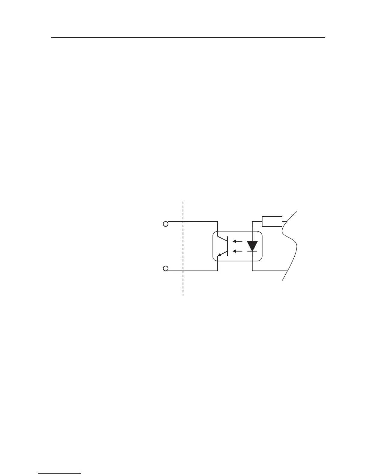
The internal circuit for these terminals is arranged as illustrated below. Terminals of Ext_GPOUT_P and
those of Ext_GPOUT_N are combined to make up eight sets of terminals in all, each set being a combination
of terminals with smaller pin numbers.
Ext_GPOUT_P
Ext_GPOUT_N
Absolute max. rating: 50mA
Pin No. : 9 10 11 12 13 14 15 16
Pin No. : 28 29 30 31 32 33 34 35
GPI/O terminal Projector interior
Photo coupler
The photo coupler in the above illustration is intended for use in output circuitry, actually installed in the
INTERFACE Board of the Cinema circuit.
It is not for IC9501 ~ IC9508 on this GPIO PWB.
When these terminals are used, a DC power supply (+) should be applied to the terminal side of Ext_GPOUT_P
and a DC power supply (-) or GND should be applied to the terminal side of Ext_GPOUT_N. For the limitation
of current between power supply or GND and terminals, a resistor should be connected in series so that the
collector current of the photo coupler transistor cannot exceed the absolute maximum rating (50mA).
If this resistor is omitted, a heavy current may be carried between the collector and the emitter of the transistor
when the photo coupler is turned ON, thus giving rise to destruction in the photo coupler.
This output terminal provides an output generated from the Cinema circuit (INTERFACE Board). Contents of
this output (H/L logic, output timing) can be set up with the microprogram for the Cinema circuit.
This output signal is used when control timing pulses, etc. are generated for the right/left eye LCD shutter
and others at the time of Active 3D System structuring.