“Confidential, Do Not Duplicate without written authorization from NEC.”
8-31
CIRCUIT DESCRIPTION
FSB PWB (Formatter Satellite Board)
PWC-4670 (RED/GREEN)/4671(BLUE)
In the Cinema circuit, this board performs data formatting for the VIDEO processor and the DMD.
The video data input is entered in the LVDS (2.5V) 16-pair format.
After passing through various functional processing of Item 1 below at U1, the data are transmitted to the DMD
in the LVDS (2.5V) 64-pair format.
PWC-4670 is used to drive the red and green DMD and PWC-4671 is used to drive the blue DMD, respectively.
The DMD and the boards are connected through the interposer “8810-001” made by Inter Con System, Inc.
Circuits and behaviors of the respective channel boards are identical with each other.
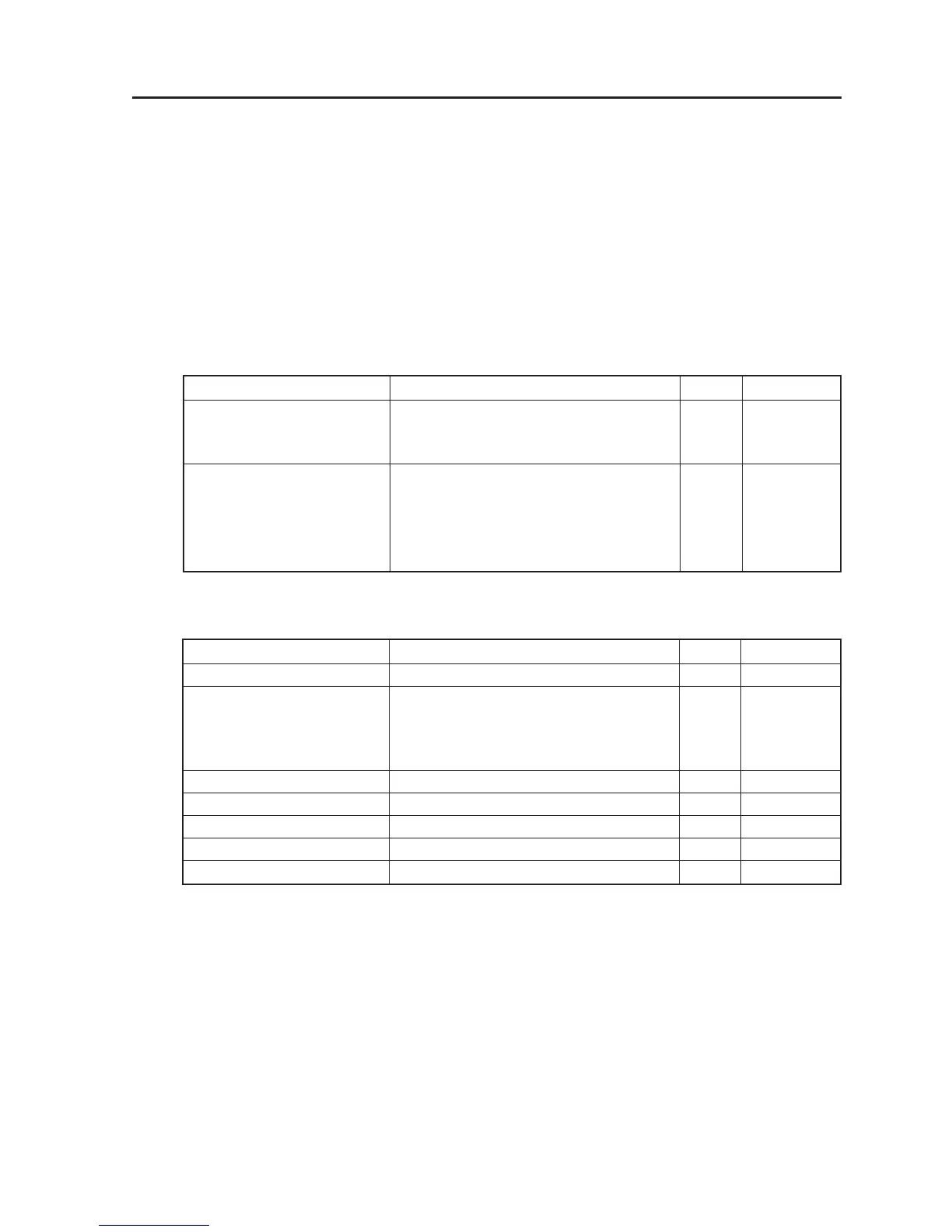
Signal Name Description I/O Type
SAT_PWRGOOD Main Power Status I 2.5V LVCMOS
A high value indicates all supplies are
within operating voltage range.
SAT_RSTZ Hardware Reset I 2.5V LVCMOS
Asynchronous Reset (Asserted LOW).
When asserted, the FPGA will be initialized
to the power up state and remain so until
SAT_RSTZ is de-asserted.
Signal Name Description I/O Type
SAT_CLK_P/N Input Data Clock ? 165MHz I 2.5V LVDS
SAT_DATA_P/N (15:0) Input Pixel/Control Data I 2.5V LVDS
Video synch signals (Vsync, Hsync &
Actdata) are embedded in the 16 bit
data word.
SAT_TXDATA_P/N Input register and setup control data I 2.5V LVDS
SAT_RXCLK_P/N Output data clock O 2.5V LVDS
SAT_RXDATA_P/N Output register and setup control data O 2.5V LVDS
SPARE_LVDS (1:0) Input Vertical Sync I 2.5V LVDS
SPARE_LVTTL (1:0) Input Horizontal Sync I 3.3V LVTTL
1. Electrical Interface
1-1. Initialization
1-2. Satellite Data Interface ? Data & Control