9-36
“Confidential, Do Not Duplicate without written authorization from NEC.”
ASSEMBLY DIAGRAM
Diagram symbol Circuit symbol Part name Part code Q’ty Remarks
PRT1 BRACKET(CM1) 24H59941 1
PRT2 COLD MIRROR 12JS0271 1
PRT3 PLATE SPRING(CM1) 24H59961 2
SRW031 CBIMS*2*6*3KF 24V00541 4 Torque check
PRT4 BASE(CM1)B ASSY 24HS4341 1
SRW029 HHCS*3*16*3GF 24V01121 2 Torque check
PRT5 BASE(CM1)A 24H59921 1
PRT6 SPRING(WM6-10) 24C08451 3
SRW027 HHCS*4*10*3GF 24V00441 3
MIRROR ASSY
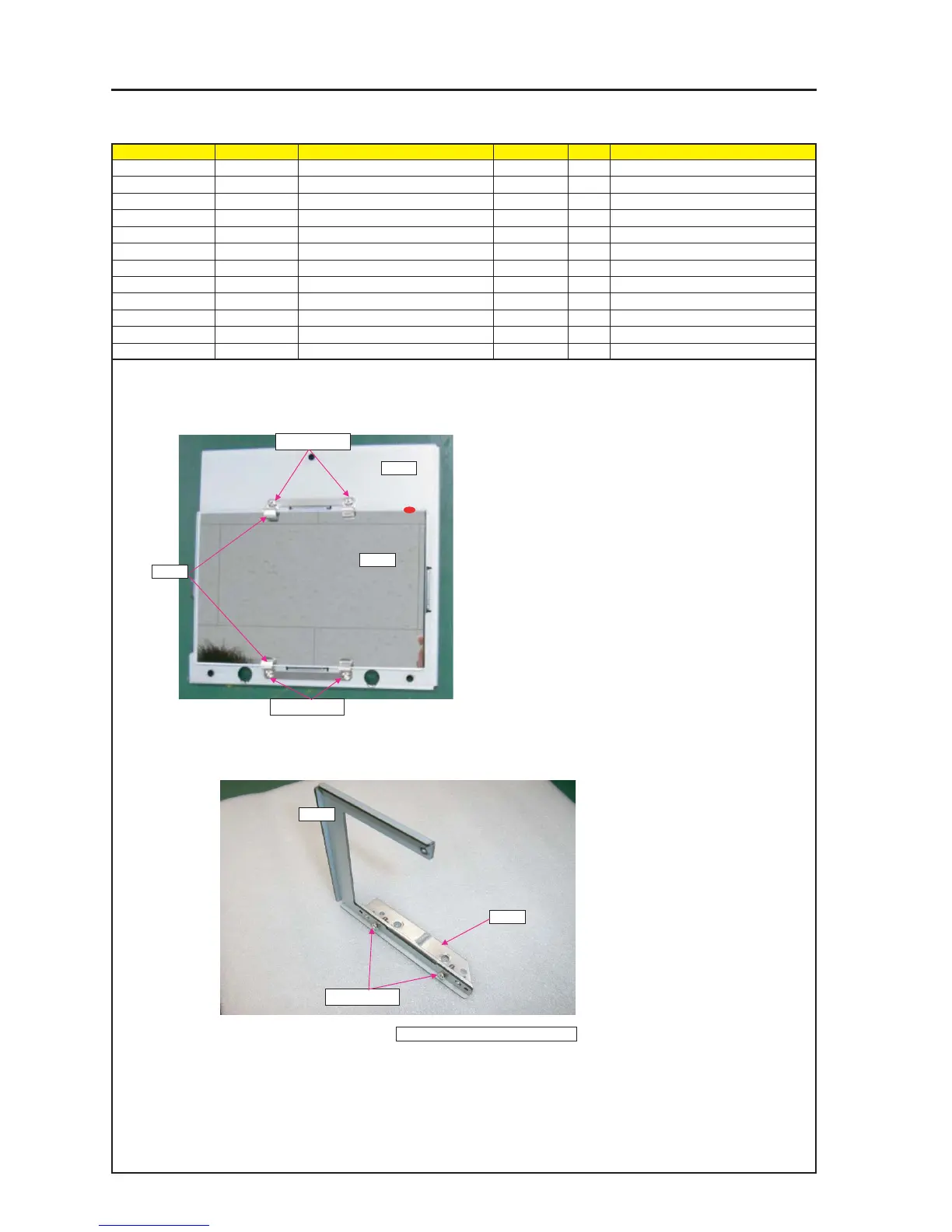
1 Put Cold Mirror over Bracket(CM1), and fix it with Plate Spring(CM1) or the screws.
CAUTION : Make sure that a red marking should be same location as picture below when putting Cold Mirror over Bracket(CM1).
Do not touch the Mirror with bare hands.
2 Attach Base(CM1)B Assy on Base(CM1)A.
PRT1
PRT2
PRT3
SRW031 X2
SRW031 X2
PRT5
PRT4
SRW031 X2
3 Adjust the positioning guide pin.