9-37
“Confidential, Do Not Duplicate without written authorization from NEC.”
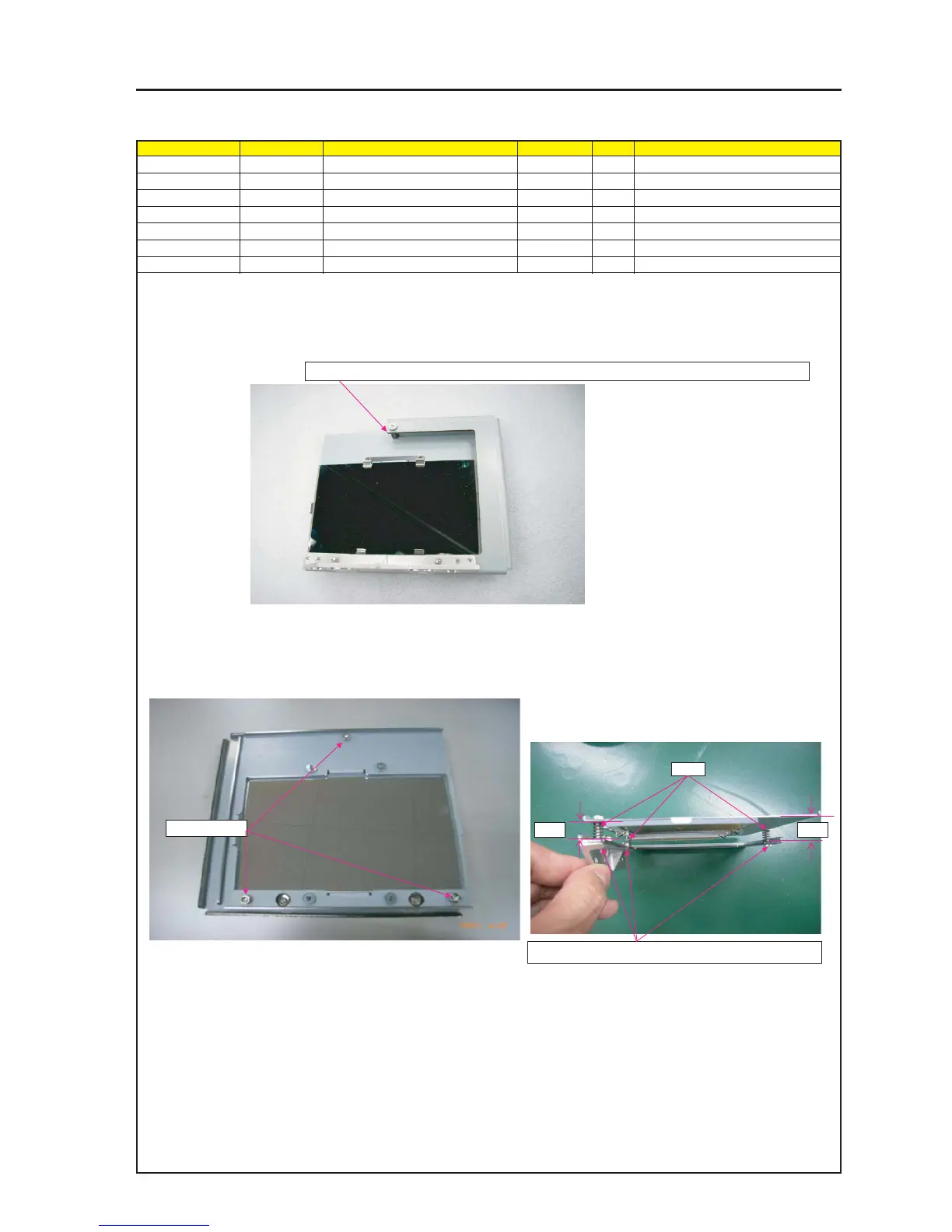
ASSEMBLY DIAGRAM
MIRROR ASSY (2)
Diagram symbol Circuit symbol Part name Part code Q’ty Remarks
PRT1 SPRING(WM6-10) 24C08451 3
SRW027 HHCS*4*10*3GF 24V00441 3
GLUE,SCREW LOCK 92201082
1 Assemble the Bracket (CM1) where the Base (CM1) A and the Cold Mirror are mounted.
At that time, put the Spring (WM6-10) in the specified place and tighten screws in the state that the above-mentioned Bracket (CM1) is placed.
The respective screws should be tightened temporarily. They should not be tightened all at once.
SRW027 X3P
5mm 5mm
PRT1
2 Put Springs (3 positions) in the Bracket (CM1) where the Base (CM1) A and the Cold Mirror are mounted.
3 Apply an exclusive gap securing jig to the section between the
Base (CM1) A and the Bracket (CM1), and tighten screws.
Use an exclusive jig to secure the unified gap of 5mm required.
4 Insert springs (3 positions) in the section between the
mounting metal fittings (CM1) and the Base (CM1) A, and
tighten screws. Control the gap of [5mm].
(Use a jig for gap control.)
5 Attach the glue screw lock to the groove side of a screw.