9-49
“Confidential, Do Not Duplicate without written authorization from NEC.”
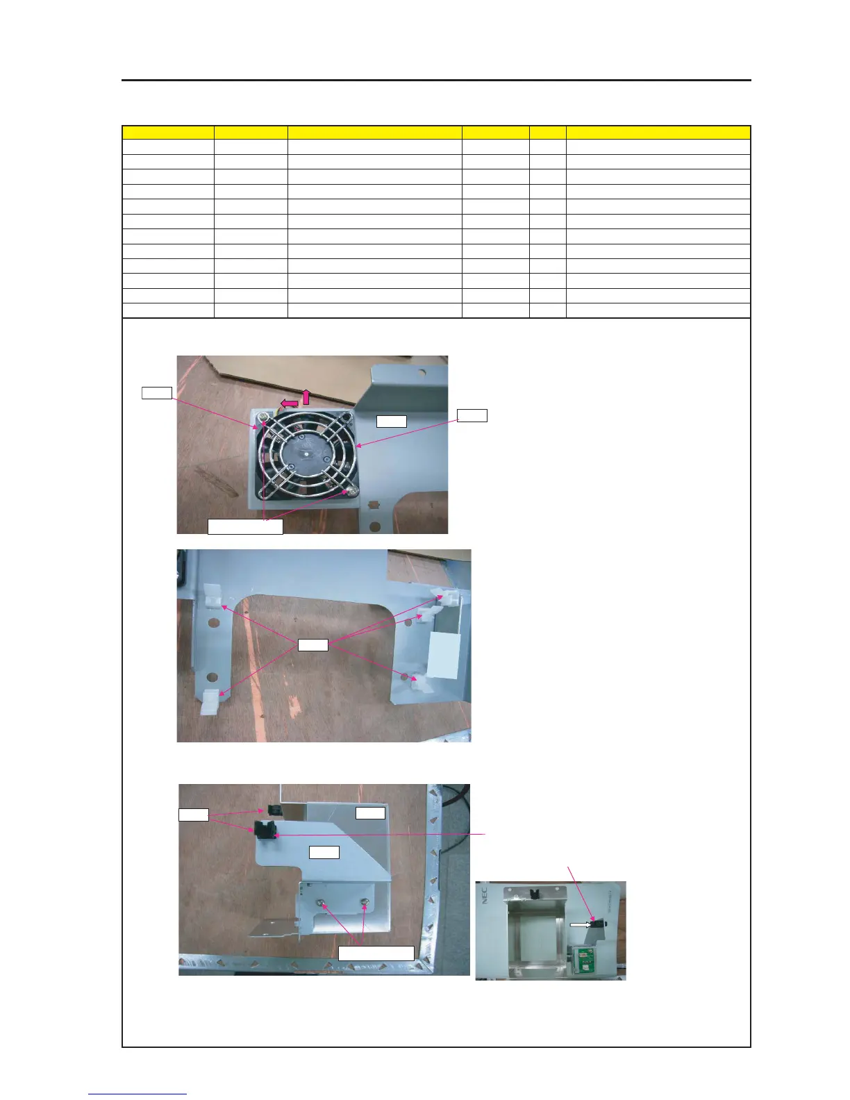
ASSEMBLY DIAGRAM
LIQUID COOLER UNIT 1
Diagram symbol Circuit symbol Part name Part code Q’ty Remarks
PRT1 BASE(TANK) ASSY 24HS4371 1
PRT2 DCFAN 2406KL 3N170096 1
PRT3 FINGER GURD 24C04131 2
SRW108 PL-CPIMS*3*25*3GF 24V00301 2 Torque check
PRT4 PC SUPPORT(H8) 12281531 5
PRT5 BASE(RADIATOR) 24H60321 1
PRT6 BASE(PUMP)ASSY 24HS4311 1
SRW080 PL-CPIMS*4*10*3KF 24V00461 2 Torque check
PRT7 HOLDER(0828) 24C08371 3
PRT1
PRT3
1 Mount DC FAN on BASE(TANK)ASSY.
2 Mount DC FAN in the direction of an arrow.
Attach FINGER GURD on front-back both sides.
SRW108 X2P
PRT2
PRT4
3 Attach PC SUPPORT(H8) on BASE(TANK)ASSY.
4 Assemble the base (radiator) and the base (pump).
Each base shall be provided with the rod holder.
PRT5
PRT6
PRT7
* Installation (insertion) is backward direction
* Right installation (insertion) direction
SRW080 X2P