9-51
“Confidential, Do Not Duplicate without written authorization from NEC.”
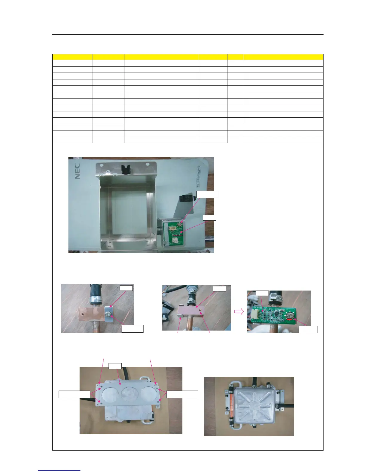
ASSEMBLY DIAGRAM
LIQUID COOLER UNIT 2
Diagram symbol Circuit symbol Part name Part code Q’ty Remarks
PRT1 RELAY PWB ASSY 1
SRW128 SCREW,PL-CPIMS*3*8*3GF 24V00111 1 Torque check
PRT2 BRACKET(STOPPER) 24H60921 1
SRW064 SCREW,PL-CPIMS*3*8*3GF 24V00111 1 Torque check
PRT3 SHEET(SERMAL) 24J34891 1
PRT4 TSENS PWB ASSY 1
SRW130 SCR(PPS M3*8) 24N08231 1 Torque check
PRT5 HOLDER(TANK) 24H51671 1
SRW005 PL-CPIMS*4*10*3KF 24V00461 4 Torque check
GLUE,SCREW LOCK 92201082
PRT1
1 Attach RELAY PWB on BASE (PUMP).
2 Attach TAMPER PWB on BRACKET (TAMPER) A.
SRW128
4 The SHEET (THERMAL) shall be mounted
opposite to the BRACKET (STOPPER).
The screw holes of the SHEET (THERMAL)
shall be symmetrically allocated based on
the BRACKET (STOPPER).
6 Mount the holder (tank) on the tank block of the liquid cooler unit.
5 Attach TSENS PWB ASSY on SHEET
(THERMAL).
PRT3
PRT5
SRW005 X2PSRW005 X2P
* When attaching TANK on FRAM ASSY.
Right side
Left side
BRACKET (STOPPER)
The screw hole
position of SHEET
(THERMAL).
PRT2
3 Attach BRACKET (STOPPER) faced up the]
cooling connection surface on right side.
SRW064
7 Apply GLUE,SCREW LOCK.
* Screws shall be mounted from tank side.
PRT4
SRW130