9-52
“Confidential, Do Not Duplicate without written authorization from NEC.”
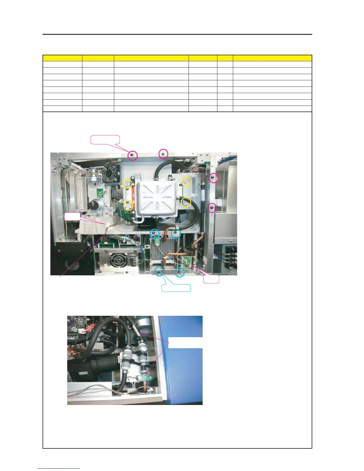
ASSEMBLY DIAGRAM
Diagram symbol Circuit symbol Part name Part code Q’ty Remarks
SRW083 PL-CPIMS*4*10*3KF 24V00461 4 Torque check
SRW049 PL-CPIMS*4*10*3KF 24V00461 4 Torque check
PRT1 CABLE CLIP(FCA-10) 24C02841 1
PRT2 BAND (L=100, T18R) 24C09121 1
LIQUID COOLER UNIT 4
1 Install the LIQUID COOLER UNIT ASSY on the FRAME ASSY of the tank block.
2 Install the radiator block of the LIQUID COOLER UNIT ASSY on the FRAME ASSY.
3 Fix the radiator block of the LIQUID
COOLER UNIT with PC holders.
X4 positions
SRW083 X4P
SRW049 X4P
PRT1
PRT1
4 Fasten the Connector (PSC) with CABLE CLIPs (FCA-10).
In this case, it shall not be made to enter the standby
power supply area crossing the AC Cable.
5 Connect the joint blocks (tank side and prism side) of the LIQUID COOLER UNIT ASSY block
and fix the connecting blocks with straps.
6 Joint (FSB-R Board side) label side of the LIQUID COOLER UNIT ASSY
Connect it to the same LABEL side (PUMP side).