9-53
“Confidential, Do Not Duplicate without written authorization from NEC.”
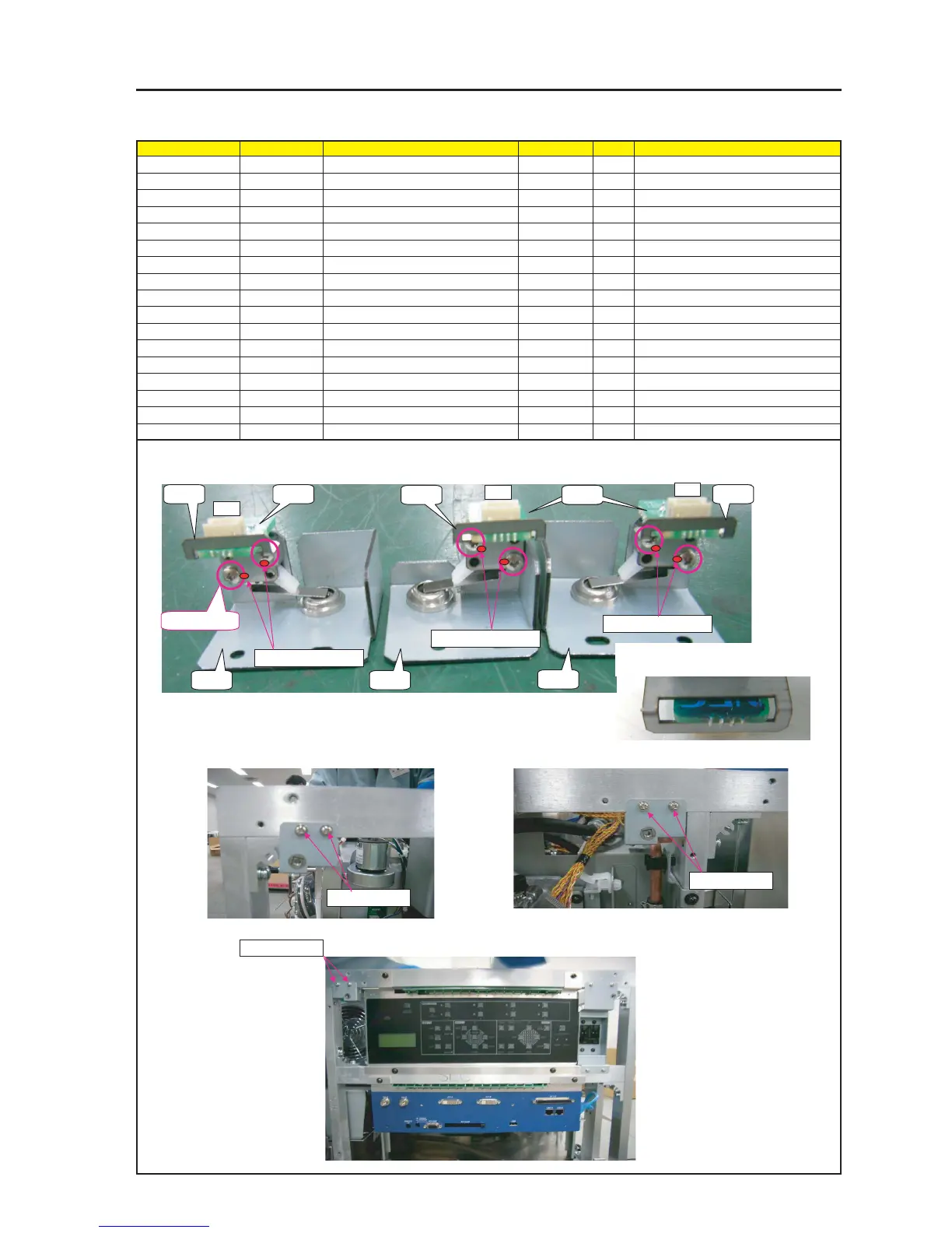
ASSEMBLY DIAGRAM
TAMP
Diagram symbol Circuit symbol Part name Part code Q’ty Remarks
PWB1 ETC3_PWB PWB ASSY 81N94Z01 1
PWB2 ETC3_PWB PWB ASSY 81N94Z01 1
PRT1 HOLDING PLATE(TAMPER PWB) 24H61171 3
PRT2 BRACKET(TAMPER)B 24H60421 1
SRW053 SCREW,PL-CPIMS*3*8*3GF 24V00111 2 Torque check
PRT3 BRACKET(TAMPER)C 24H60431 1
SRW054 SCREW,PL-CPIMS*3*8*3GF 24V00111 2 Torque check
PRT4 BRACKET(TAMPER)D 24H60441 1
SRW055 SCREW,PL-CPIMS*3*8*3GF 24V00111 2 Torque check
SRW143 CBIMS*2*8*3GF 24V01031 6 Torque check
T4 CN3P(T4)700W,1061-26 7NW3W092 1
T5 CN3P(T5)900W,1061-26 7NW3W093 1
T6 CN3P(T6)1050W,1061-26 7NW3W094 1
GLUE,SCREW LOCK 92201082
1 Attach TAMPER PWB ASSY on BRACKET (TAMPER) B, C, D.
* Insert HOLDING PLATE( TAMPER PWB) into between BRACKET and TAMPER PWB ASSY.
SRW053 X2P
SRW054 X2P
SRW055 X2P
3 Mount BRACKET (TAMPER)B ASSY.
4 Mount BRACKET (TAMPER) D ASSY.
5 Mount BRACKET (TAMPER) C ASSY.
PRT1
PRT1
PRT1PWB1
PWB2PWB2
SRW*** x 6P
PRT2PRT3
PRT4
T4
T5
T6
2 Insert TAMPER PWB ASSY into the apertural
area of HOLDING PLATE (TAMPER PWB).
GLUE,SCREW LOCK
GLUE,SCREW LOCK
GLUE,SCREW LOCK