9-54
“Confidential, Do Not Duplicate without written authorization from NEC.”
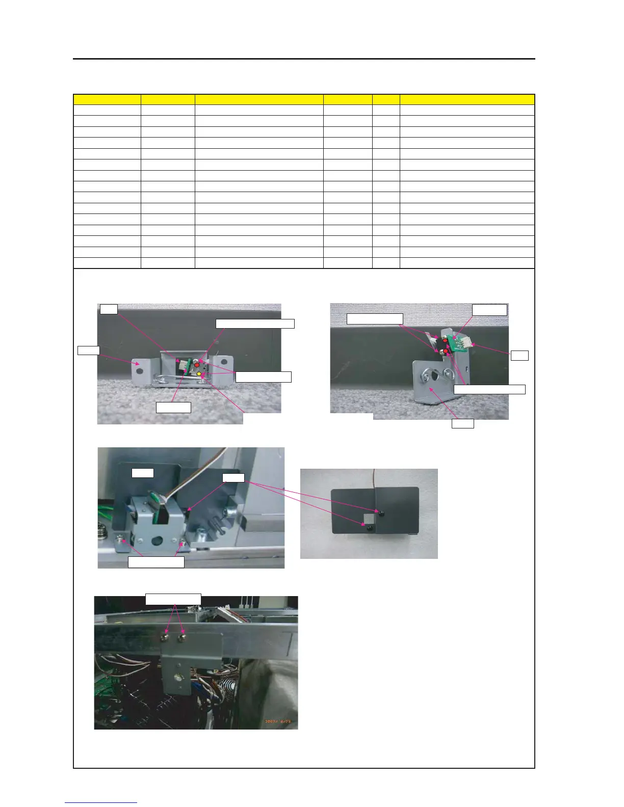
ASSEMBLY DIAGRAM
Diagram symbol Circuit symbol Part name Part code Q’ty Remarks
PRT1 BRACKET(FB) B ASSY 24HS4401 1
SRW074 SCREW,PL-CPIMS*3*8*3GF 24V00111 2 Torque check
PRT2 BRACKET(FE) B ASSY 24HS4411 1
SRW075 SCREW,PL-CPIMS*3*8*3GF 24V00111 2 Torque check
SRW143 CBIMS*2*8*3GF 24V01031 4 Torque check
PWB1 ETC3_PWB PWB ASSY 81N94Z01 1
PRT3 HOLDING PLATE(TAMPER PWB) 24H61171 1
T2 CN3P(T2)275W,1061-26 7NW3W090 1
T6 CN3P(T6)1050W,1061-26 7NW3W094 1
PRT4 BARRIER(TAMPER F) 24J34911 1
PRT5 RIVET,PUSH(NRP-345) 24C06391 2
GLUE,SCREW LOCK 92201082
BRACKET
PRT1
PRT2
1 Attach TAMPER PWB ASSY on BRACKET (FB) B ASSY.
Mount one of SRW143 on the other side.
SRW143 X1P
PWB1
2 Mount TAMPER PWB ASSY on BRACKET (FE) B ASSY.
SRW143 X2P
PWB1
3 Insert it in-between BRACKET and TAMPER PWB ASSY.
6 Mount BRACKET(FE)B ASSY.
SRW075 X2P
T2
T6
5 Mount the BARRIER (TAMPER F) on the BRACKET (FB) B ASSY
by means of RIVETs and PUSH (NRP-345).
4 Attach BARRIER(TAMPER F) from rear side of
RIVET,PUSH(NRP-345).
PRT5
PRT4
SRW074 X2P
GLUE,SCREW LOCK
GLUE,SCREW LOCK
Attach this screw the other side of SW.