9-56
“Confidential, Do Not Duplicate without written authorization from NEC.”
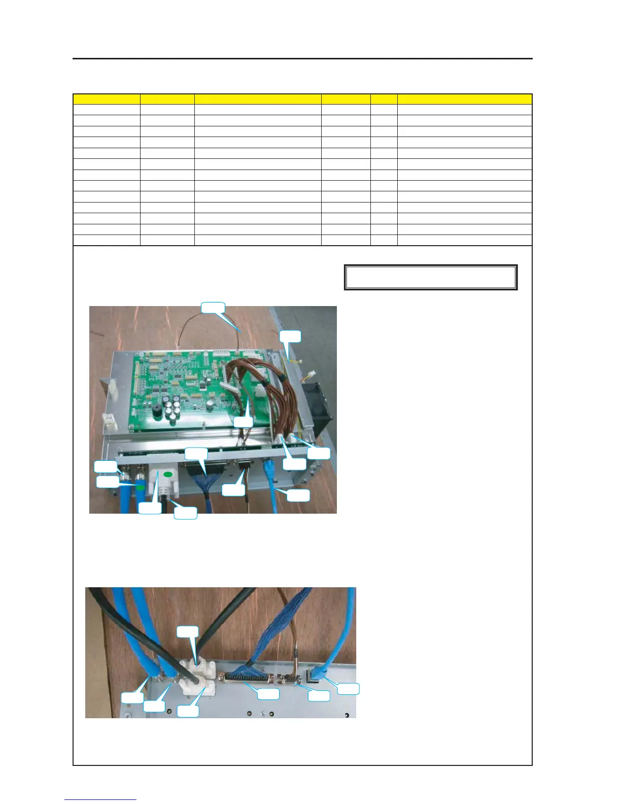
ASSEMBLY DIAGRAM
Diagram symbol Circuit symbol Part name Part code Q’ty Remarks
CN1 LAN CABLE LAN 0.33M PCRJE0033 7N520058 1
CN2 CT CN9P(CT)250W,1061-26 7NW9W010 1
CN3 GP CN37-40P(GP)250W,1571-28 7NWLW046 1
CN4 DVI-D CABLE DVI-D SA0509049 7N520056 2
CN5 BNC CABLE BNC D5FBC0042-SA 7N520062 2
CN6 N10 & N11 CN10P(N10)200W,1015-18 7NW0W022 2
CN7 FP CN4-5P(PF)200W, 1061-26 7NW4W042 1
CN8 LAN CN2P(LAN)270W,1061-24 7NW2W033 1
CN9 T1 CN3P(T1)225W,1061-26 7NW3W089 1
TI Shield MT1
1 Insert the respective connector cables in the TI Shield Case Sassy.
Caution: After making connections, the CN-CT and CN-GP connectors shall be
fastened with the accessory studs.
Caution: After making connections, the CN-GP cable shall be fastened with the
accessory screws.
CN1
CN2
CN3
CN5
CN5
CN4
CN4
CN6
CN6
CN9
CN7
CN8
CN5
CN5
CN4
CN4
CN3
CN2
CN1
[Caution] Measures against static charges
Wrist straps shall be used while boards are handled.
2 Give a green marking to the A terminal side.
(Both sides)