9-57
“Confidential, Do Not Duplicate without written authorization from NEC.”
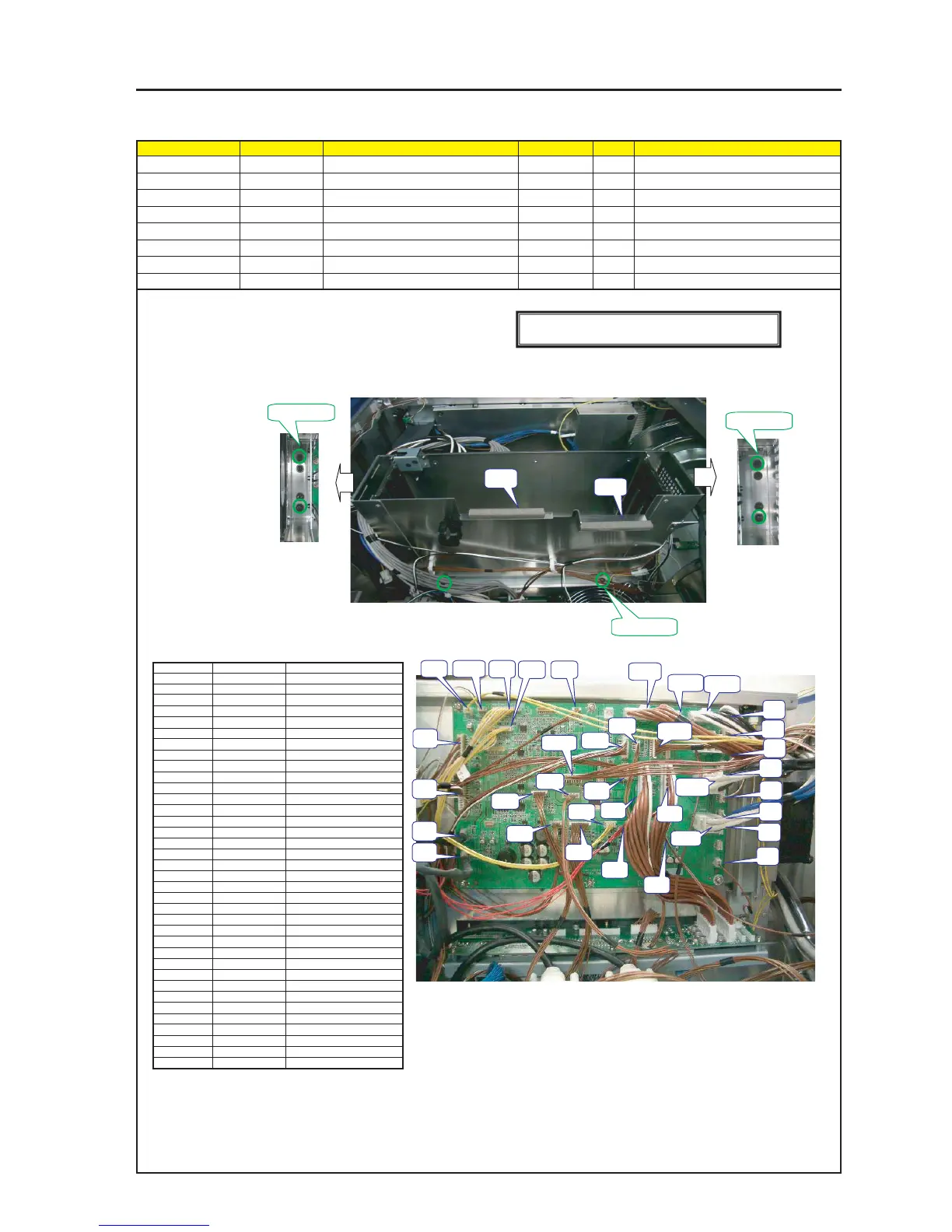
ASSEMBLY DIAGRAM
TI Shield MT2
Diagram symbol Circuit symbol Part name Part code Q’ty Remarks
SRW084 PL-CPIMS*4*10*3KF 24V00461 6 Torque check
CN1 CN2-WP(TH)1325X,3265-24 7NW2V001 1
PRT1 GASKET(STG15-10) 24C06081 1 70mm
PRT2 GASKET(STG7-10) 24C08591 1 90mm
1 After the gaskets (STG10-10) and (STG7-10) have been cut into pieces of 70mm and 110mm respectively,
they shall be stuck to the TI Shield Case Sassy.
2 Fasten the TI Shield Case Sassy.
3 Insert the respective connectors in the PJDIV PWB ASSY.
Connector
COV
TH
TE1
TE2
F1
F2
F3
F4
PY
J100
SIO
CF
PSC
CE
PU
PSS1
CP
PF
PSM4
DO
N10
N11
STA
ANA
LAN1
PSM1
PSM2
PSM3
T1
T2
T3
T4
T5
T6
T7
TA
Connect to
PJDIV PWB
PJDIV PWB
PJDIV PWB
PJDIV PWB
PJDIV PWB
PJDIV PWB
PJDIV PWB
PJDIV PWB
PJDIV PWB
PJDIV PWB
PJDIV PWB
PJDIV PWB
PJDIV PWB
PJDIV PWB
PJDIV PWB
PJDIV PWB
PJDIV PWB
PJDIV PWB
PJDIV PWB
PJDIV PWB
PJDIV PWB
PJDIV PWB
PJDIV PWB
PJDIV PWB
PJDIV PWB
PJDIV PWB
PJDIV PWB
PJDIV PWB
PJDIV PWB
PJDIV PWB
PJDIV PWB
PJDIV PWB
PJDIV PWB
PJDIV PWB
PJDIV PWB
PJDIV PWB
Connect from
COVER
THERMOSTAT
TSENS PWB
TSENS PWB
FAN(Tube)
FAN(Prism)
FAN(Lamp)
FAN(Lamp)
LENS PWB
MOTOR
CPU PWB
CPU PWB
AC PWB
CPU PWB
RELAY PWB
STANDBY PS
CPU PWB
MOTHER PWB
GPSU
DVI/OUT PWB
MOTHER PWB
MOTHER PWB
SLED/A PWB
ANA
ETHER PWB
GPSU
GPSU
GPSU
FIPS(TI Case)
FIPS(Lens hood)
FIPS(Left to the front)
FIPS (Right to the front)
FIPS (Left to the rear)
FIPS(FRONT)
FIPS (Right to the rear)
MOTHER PWB
SRW084 X 2
SRW084 X 2
SRW084 X 2
COVTH TE1
TE2
F1
F2
F3
F4
PY
J100
SIO
CF
PSC
CE
PU
PSS1
CP
PF
PSM4
DO
N10
N11
STA
ANA
LAN1
PSM3
PSM2
PSM1
T1
T2
T3
T4
T6
T5
T7
PRT1
PRT2
[Caution] Measures against static charges
Wrist straps shall be used while boards are handled.
TA