9-58
“Confidential, Do Not Duplicate without written authorization from NEC.”
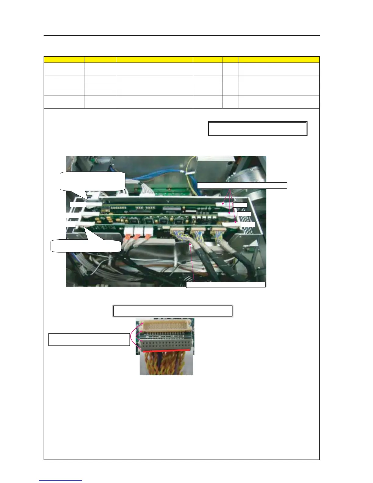
ASSEMBLY DIAGRAM
Diagram symbol Circuit symbol Part name Part code Q’ty Remarks
PWB1 PROCESSOR 2506937-0002 7N950861 1
PWB2 INTERFACE 2506940-0002 7N950851 1
PWB3 FFIB_PWB ASSY 81N94F01 1 Torque check
TI Shield MT3
1 Install the Interface Board and the Processor Board on the TI Shield Case.
Caution: Each board shall be inserted assuredly and there shall be no defects
such as lifting and tilting.
2 Mount the FFIB PWB ASSY on the TI Shield Case.
Caution: The respective connectors shall be inserted after the FFIB PWB ASSY has been inserted in the TI Shield Case completely.
When connectors are inserted or pulled out, or in the case of cabling, stresses may be applied to the respective FMT PWB SASSY
and FFIB PWB ASSY. Therefore, connectors shall not be pulled violently.
3 Insert in the FFIB the J1/J7 connectors from the PRISM ASSY.
The J7 connector has a direction for insertion (polarity).
Interface
Processor
FFIB
[Caution] Measures against static charges
Wrist straps shall be used while boards are handled.
* Check the surface unevenness of the housing before insertion.
PWB1
PWB2
PWB3
Except for the FFIB, the respective
ejectors shall be free from plays
and such deficiencies.
It shall be inserted assuredly.
Press this part during board insertion.
Red marking side of connector corresponds
to the upper surface of the post (hollow).
This direction shall be examined before insertion.
Cables shall not override the metallic plate.