9-59
“Confidential, Do Not Duplicate without written authorization from NEC.”
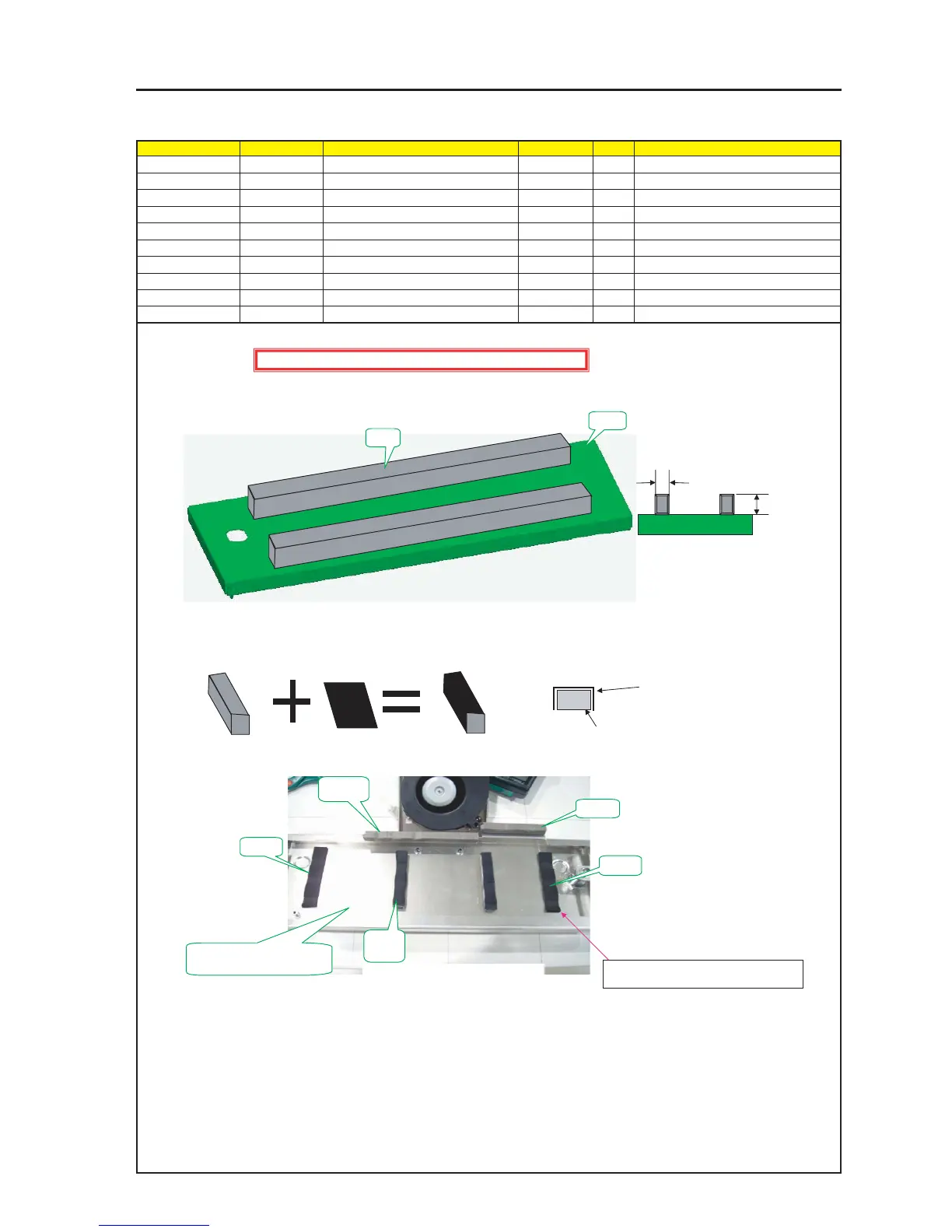
ASSEMBLY DIAGRAM
TI EMI
Diagram symbol Circuit symbol Part name Part code Q’ty Remarks
PRT1 SHIELD CASE E 24H61041 1
PRT2 GASKET(STG15-10) 24C06081 2 250mm
PRT3 GASKET(STG15-10) 24C06081 1 70mm
PRT4 GASKET(STG10-10) 24C08351 1 120mm
PRT5 GASKET(STG8-10) 24C05341 2 70mm
PRT6 CUSHION(80*15*T4) 24J28641 2
PRT7 ACETATE CLOTH TAPE 9R030010 4 70mm
1 Cut the gasket (STG15-10) to a piece of 250mm and stick it to the top surface of the
Shield Case E.
2 Cut an acetate cloth tape into a piece of 70mm and stick it to cover the Gasket (STG8-10) that has been cut into the same piece of 70mm.
3 Cut the gasket (STG8-10) into 70mm X 2P processed in the same manner as above and stick it to inside of the top surface of the Shield Case E.
* A = 10mm / B = 15mm
A
B
PRT1
PRT2
PRT6
[Caution] EMI (Electromagnetic Interference: Radio interference noise)
PRT6
PRT4
PRT5
PRT7
GASKET (STG8-10) 70mm
The adhesion side shall be faced downwards.
Drawing as seen from the cross section
Acetate Cloth Tape 70mm
PRT3
Corners of the CUSHION (80*15*T4) shall
be stuck according to the round boss.
To be stuck evenly between CUSHIONs.
To be stuck according to the
keyhole edge.