9-60
“Confidential, Do Not Duplicate without written authorization from NEC.”
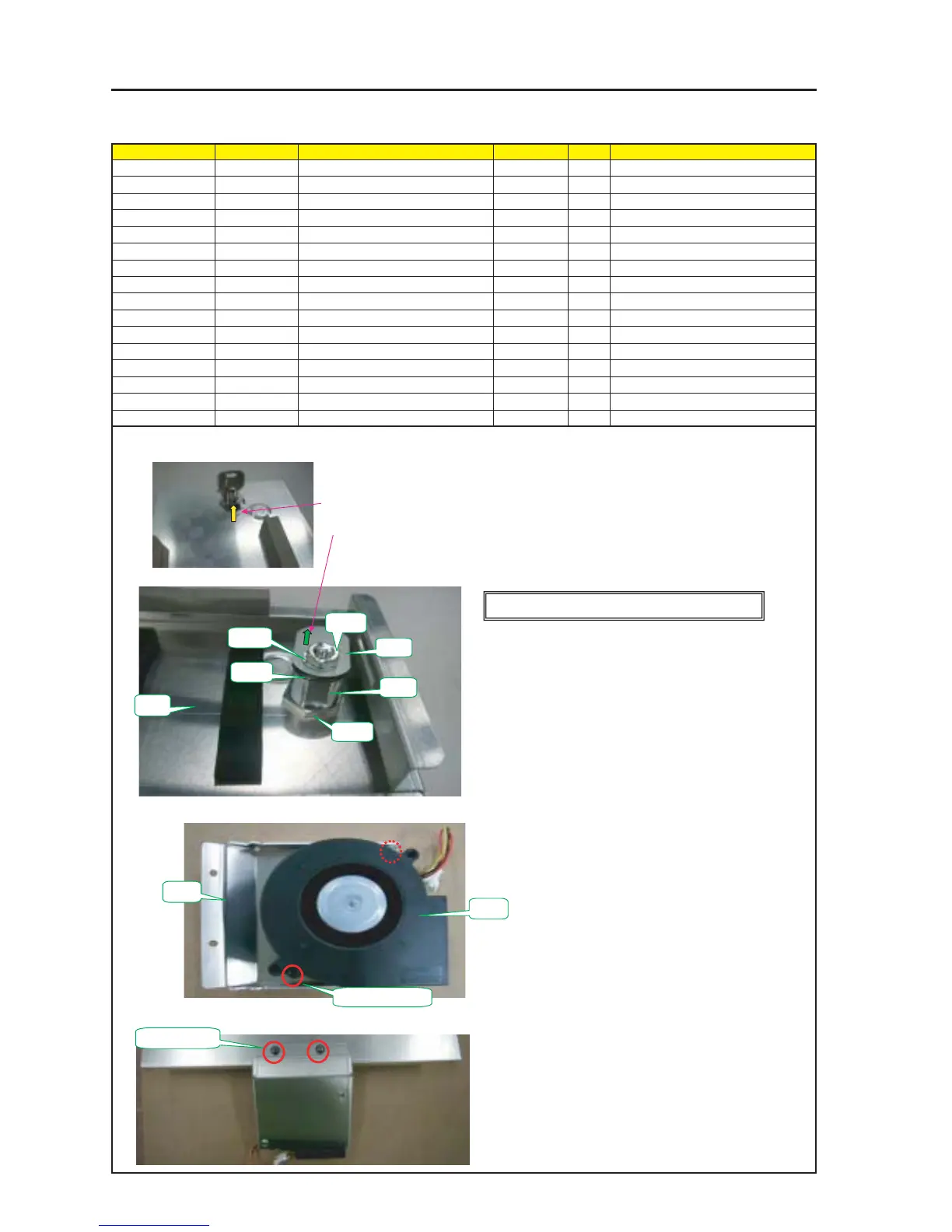
ASSEMBLY DIAGRAM
Diagram symbol Circuit symbol Part name Part code Q’ty Remarks
PRT1 SHIELD CASE E 24H61041 1
PRT2 CAM(LOCK)TI 24H61071 1
PRT3 KEY(NS-804) 24C09301 1 Number control
PRT4 NUT(larg) 1 Torque check
PRT5 NUT (small) 1 Torque check
PRT6 WASHER 1 1
PRT7 WASHER 2 1
PRT8 BRACKET(P-FAN) 24H60851 1
PRT9 DCFAN 9BAM24GD2-2 3N170100 1
SRW110 PL-CPIMS*4*10*3KF 24V00461 2 Torque check
SRW058 PL-CPIMS*4*10*3KF 24V00461 2 Torque check
TI Shield MT4
1 Mount the KEY (NS-804) and the CAM (LOCK) TI on the Shield Case E.
For the installation of the CAM (LOCK) TI, the nuts attached to the KEY (NS-804) shall be used.
3 Mount the DC FAN 9BAM24GD2-2 on the BRACKET (P-FAN).
4 Mount the DC FAN Sassy on the Shield Case E Sassy.
PRT4
PRT7
PRT5
PRT6
PRT8
PRT9
SRW110 X 2P
SRW058 X 2P
PRT1
PRT2
PRT3
[Caution] Describe the KEY number in the history sheet.
The CAM (LOCK) TI shall be installed in the posture as shown in the photo below.
2 In the state that the key is inserted (Unlocked), the notch section shall be positioned inside.
a) Remove the nut and washer, attached to the KEY (NS-804).
b) With the NUT (large), fix the KEY (NS-804) to the Shield Case E.
c) Enter the Washer 1 and the CAM (LOCK) TI in the KEY (NS-804).
d) Enter the Washer 2 and fix the CAM (LOCK) TI with the NUT (small).
Tightening torque of PRT4 : 100±5kgf•cm
Tightening torque of PRT5 : 32±2kgf•cm
Caution : Confirm that the key can be pulled out after key locking.
If it cannot be pulled out, change the direction of washer
attached to the key and reinstall it.