9-61
“Confidential, Do Not Duplicate without written authorization from NEC.”
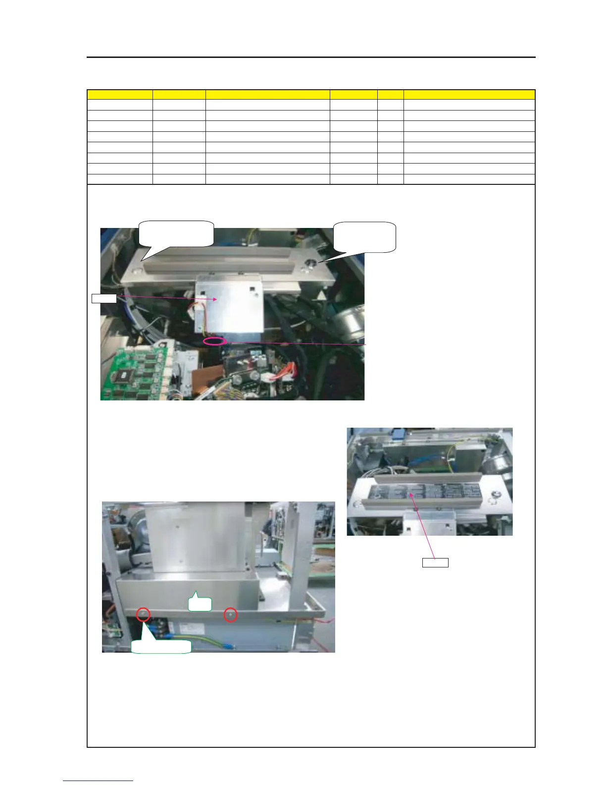
ASSEMBLY DIAGRAM
Shield MT5
Diagram symbol Circuit symbol Part name Part code Q’ty Remarks
PRT1 SHIELD PLATE(ENGINE)A 24H60091
SRW040 SCREW,PL-CPIMS*3*8*3GF 24V00111 Torque check
PRT2 CABE CLIP(FCA-10) 24C02841 1
PRT3 CAUTION LABEL(TI CONNECTO 24L64451 1
1 Mount the Shield Case E Sassy on the TI Shield Case E Sassy.
Install the KEY (NS-804) and its opposite side in such a manner of hanging them, and lock the KEY (NS-804) lastly.
Caution : Many gaskets are stuck to the
Shield Case E and the B Sassy,
and gaskets themselves can
become repulsive. In some cases,
therefore, it may be difficult to
mount the same parts.
Before tightening, confirm if each
hook is effective.
SRW040 X 2P
PRT1
PRT2
PRT3
2 Based on this side,
hook and fix it.
3 Lock the KEY
(NS-804) lastly.
5 Stick the CABLE CLIP (FCA-10) to the BRACKET (P-FAN).
Stick the FAn CABLE in positions where it does not come in
contact with the heat radiating plate of the Prism Assy.
4 To prevent the CABLEs from coming in contact
with the heat radiating plate, determine the
adhesion positions for CABLE CLIPs.
6 Stick the CAUTION LABEL (TI CONNECTOR) to the top
surface of the Shield Case E Sassy. (Almost in the center)
7 Install the SHIELD PLATE (ENGINE) A on the FRAME ASSY.