9-62
“Confidential, Do Not Duplicate without written authorization from NEC.”
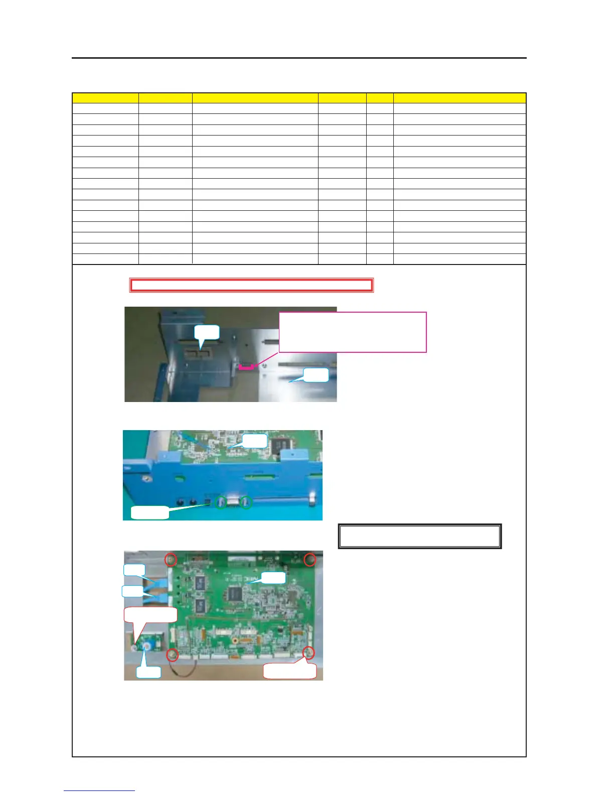
ASSEMBLY DIAGRAM
Diagram symbol Circuit symbol Part name Part code Q’ty Remarks
PRT1 BRACKET(ARM) 24H55512 1
PRT2 GASKET(LAN) 24J28981 1
PRT3 GASKET(USB) 24J29571 1
PWB1 CPU PWB Assy 81L23CA2 1
PRT4 STUD(D-SUB H*5.3) 24N08192 2 Torque check
SRW121 SCREW,PL-CPIMS*3*8*3GF 24V00111 4 Torque check
CN1 LAN CABLE LAN 0.33M PCRJE0033 7N520058 2
PWB2 S-CAP PWB ASSY 81L23CC2 1
SRW119 SCREW,PL-CPIMS*3*8*3GF 24V00111 1 Torque check
CN2 CB CN3P(CB)100W,1061-26 7NW3W066 1
CPU1
1 Stick the Gasket (LAN) to the Bracket (ARM).
2 Mount the Bracket (ARM) on the CPU_PWB ASSY.
3 Install the S-CAP PWB ASSY and insert the CN-CB.
PRT3
The GASKET (UAB) shall be stuck based on the
lower side of the USB square hole.
(The right and left sides shall be evenly balanced
based on the square hole.)
PRT1
PRT2
PWB1
PRT4 X 2
PWB1
SRW121 X 2P
SRW119 X 1P
PWB2
CN1
CN1
Caution : External parts shall be handled carefully so that they are not damaged.
[Caution] Measures against static charges
Wrist straps shall be used while boards are handled.