9-63
“Confidential, Do Not Duplicate without written authorization from NEC.”
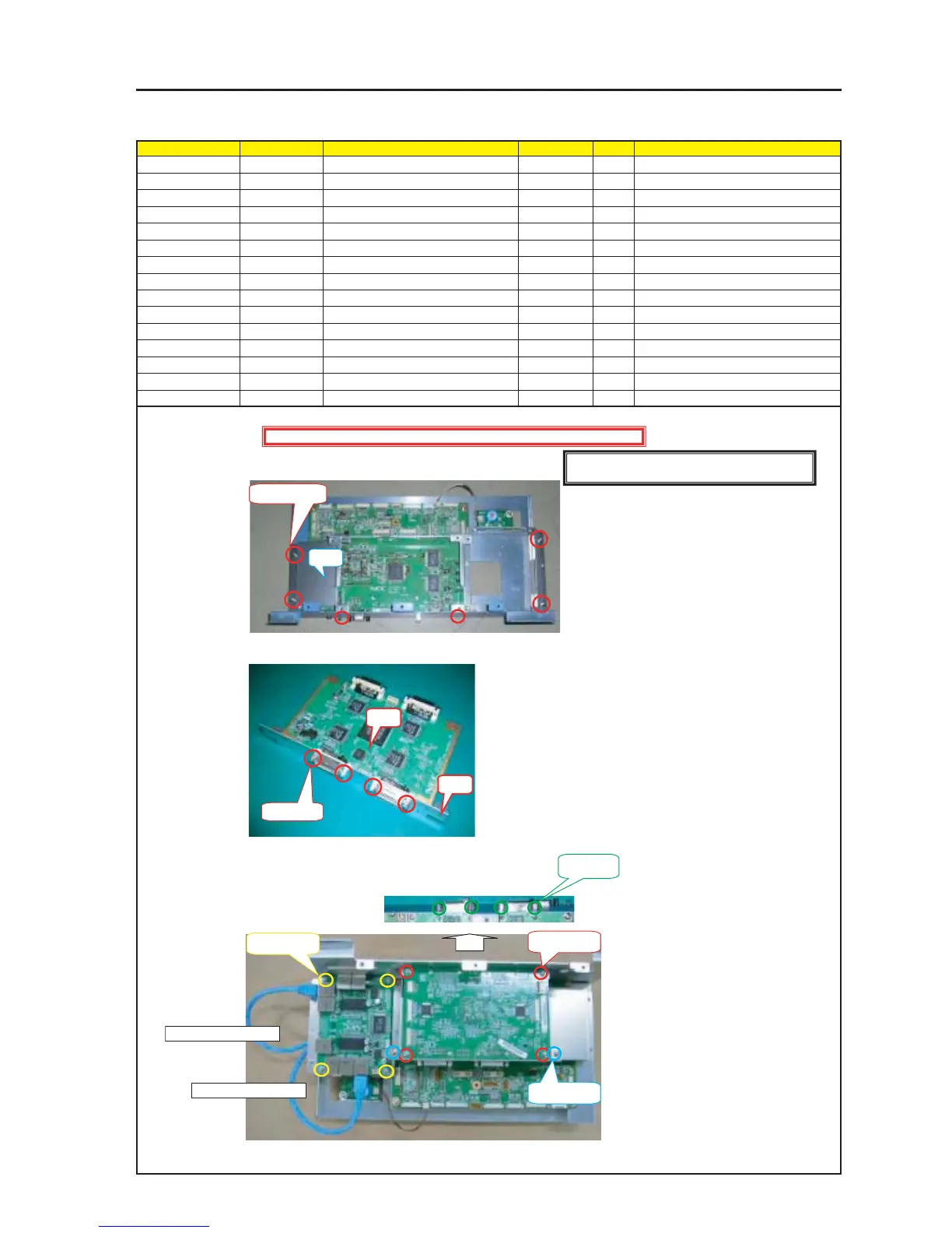
ASSEMBLY DIAGRAM
CPU2
Diagram symbol Circuit symbol Part name Part code Q’ty Remarks
PRT1 BRACKET(DVI-O) 24H55531 1
SRW0115 SCREW,PL-CPIMS*3*8*3GF 24V00111 6 Torque check
PRT2 FIXING PLATE(DVI) 24H55541 1
PWB1 DVI-OUT PWB ASSY 81L07V01 1
PRT3 STUD 4 Torque check
SRW116 SCREW,PL-CPIMS*3*8*3GF 24V00111 4 Torque check
SRW116 SCREW,PL-CPIMS*3*8*3GF 24V00111 2 Torque check
PRT4 STUD 4 Torque check
ETHER PWB ASSY 1
SRW118 SCREW,PL-CPIMS*3*8*3GF 24V00111 4 Torque check
1 Mount the Bracket (ARM) Sassy on the Bracket (DVI-O).
2 Remove the stud from the DVI-OUT PWB and use this stud for mounting after the Fxing Plate (DVI) has been removed.
3 Install the DVI-OUT PWB ASSY and the ETHER PWB ASSY on the
Bracket (ARM) Sassy.
Insert the LAN CABLE of the S CAP PWB ASSY in the ETHER PWB ASSY.
PRT1
SRW015 X 6P
PRT2
PWB1
PRT3 X 4P
PRT4 X 4P
SRW116 X 4P
SRW016 X 2P
SRW118 X 2P
Caution : External parts shall be handled carefully so that they are not damaged.
[Caution] Measures against static charges
Wrist straps shall be used while boards are handled.
From CPU PWB M7500
From CPU PWB M7400