9-64
“Confidential, Do Not Duplicate without written authorization from NEC.”
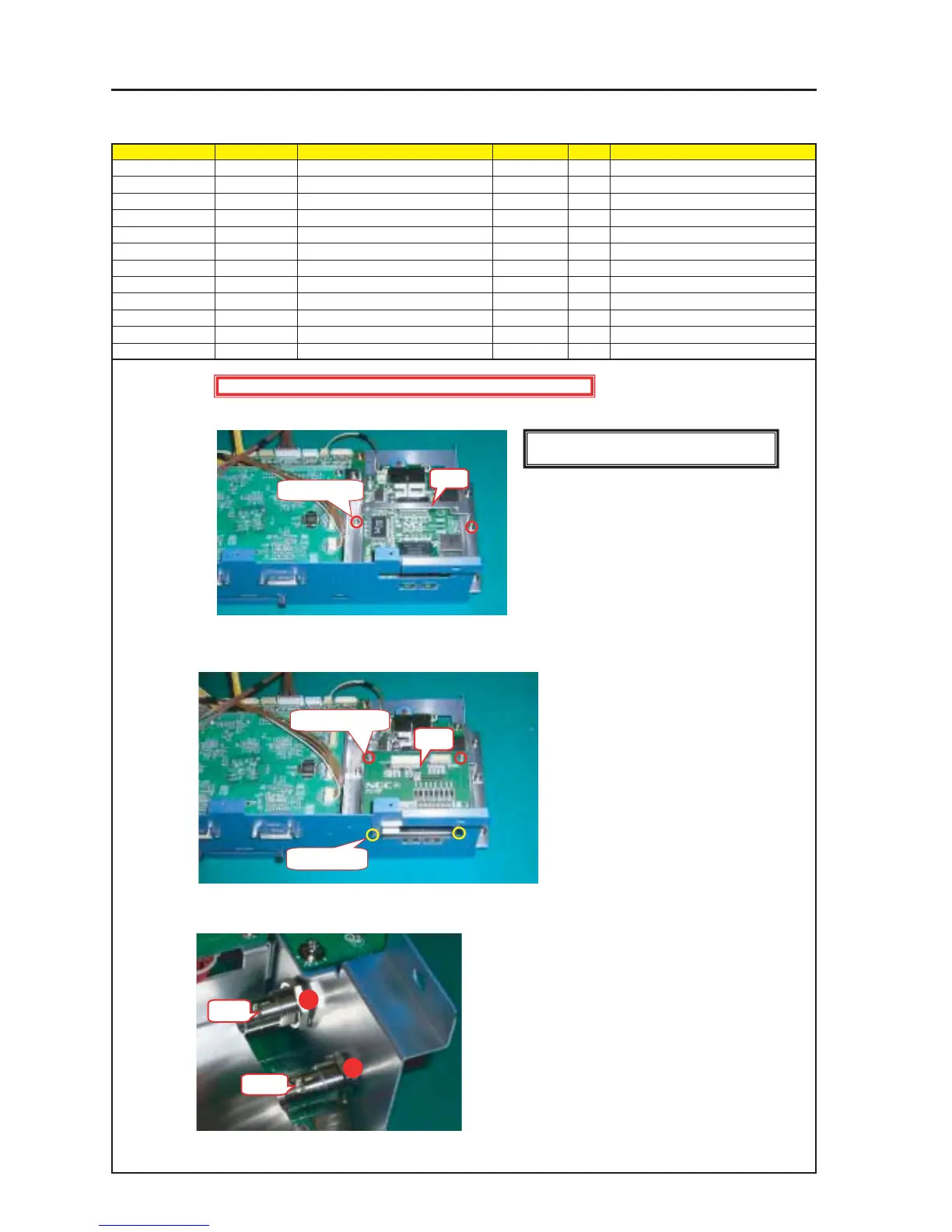
ASSEMBLY DIAGRAM
Diagram symbol Circuit symbol Part name Part code Q’ty Remarks
PRT1 BRACKET(GP) 24H55521 1
SRW014 SCREW,PL-CPIMS*3*8*3GF 24V00111 2 Torque check
PWB1 GPIO PWB ASSY 81L07YE1 1
SRW117 SCREW,PL-CPIMS*3*8*3GF 24V00111 2 Torque check
PRT2 STUD(D-SUB H*6.3) 24N08182 2 Torque check
PRT3 CONNECTOR BCJ-JR 7N030133 2
GLUE,SCREW LOCK 92201082 Adequate quantity
CPU3
1
Mount the Bracket (GP).
2
Remove the STUD from the GPIO-PWB ASSY and use this STUD for fixing.
3
Remove the nut from the connector BCG-JR. After insertion in metal fittings, use the same nut for fixing. (2 positions)
* Apply a screw lock agent after fixing.
Tightening torque : 27
±
2kgf•cm
PRT1
SRW014 X 2P
SRW117 X 2P
PRT2 X 2P
PWB1
PRT3
PRT3
Caution : External parts shall be handled carefully so that they are not damaged.
[Caution] Measures against static charges
Wrist straps shall be used while boards are handled.