9-65
“Confidential, Do Not Duplicate without written authorization from NEC.”
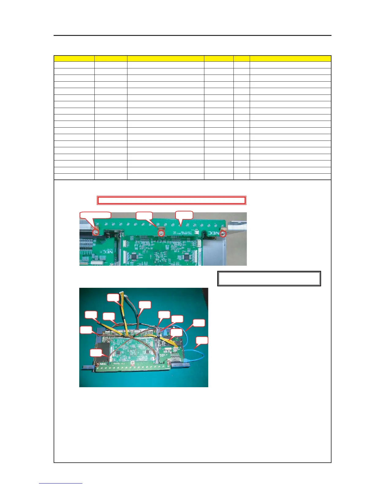
ASSEMBLY DIAGRAM
CPU4
Diagram symbol Circuit symbol Part name Part code Q’ty Remarks
PWB1 LIGHT-2 PWB ASSY 1
PRT1 PLATE SPRING(LED) 24H57591 3
SRW122 SCREW,PL-CPIMS*3*8*3GF 24V00111 3 Torque check
PRT2 BARRIER (LED) 24J35131 1
PRT3 ACETATE CLOTH TAPE 570F 9R030010 1
CN1 DO CN5P(DO)475W,1061-24 7NW5W066 1
CN2 TY CN6P(TY)325W,1061-26 7NW6W039 1
CN3 CP CN7P(CP)400W,1061-24 7NW7W030 1
CN4 CF CN10P(CF)250W,1061-28 7NW0W024 1
CN5 CE CN15P(CE)200W,1061-28 7NWEW022 1
CN6 N8 CN9P(N8)150W,1061-24 7NW9W002 1
CN7 CO CN14P(CO)180W,1061-28 7NWDW015 1
CN8 CB CN3P(CB)100W,1061-26 7NW3W066
CN9 LAN CABLE LAN 0.33M PCRJE0033 7N520058
1 Install the LIGHT-2 PWB Assy. At that time, tighten the PLATE SPRING (LED) together.
2 Insert the respective wiring materials.
PRT1
PWB1
SPW122 X 3
CN1
CN2
CN3
CN4
CN5
CN6
CN7
CN1
CN8
CN9
CN9
Caution : External parts shall be handled carefully so that they are not damaged.
[Caution] Measures against static charges
Wrist straps shall be used while boards are handled.