9-66
“Confidential, Do Not Duplicate without written authorization from NEC.”
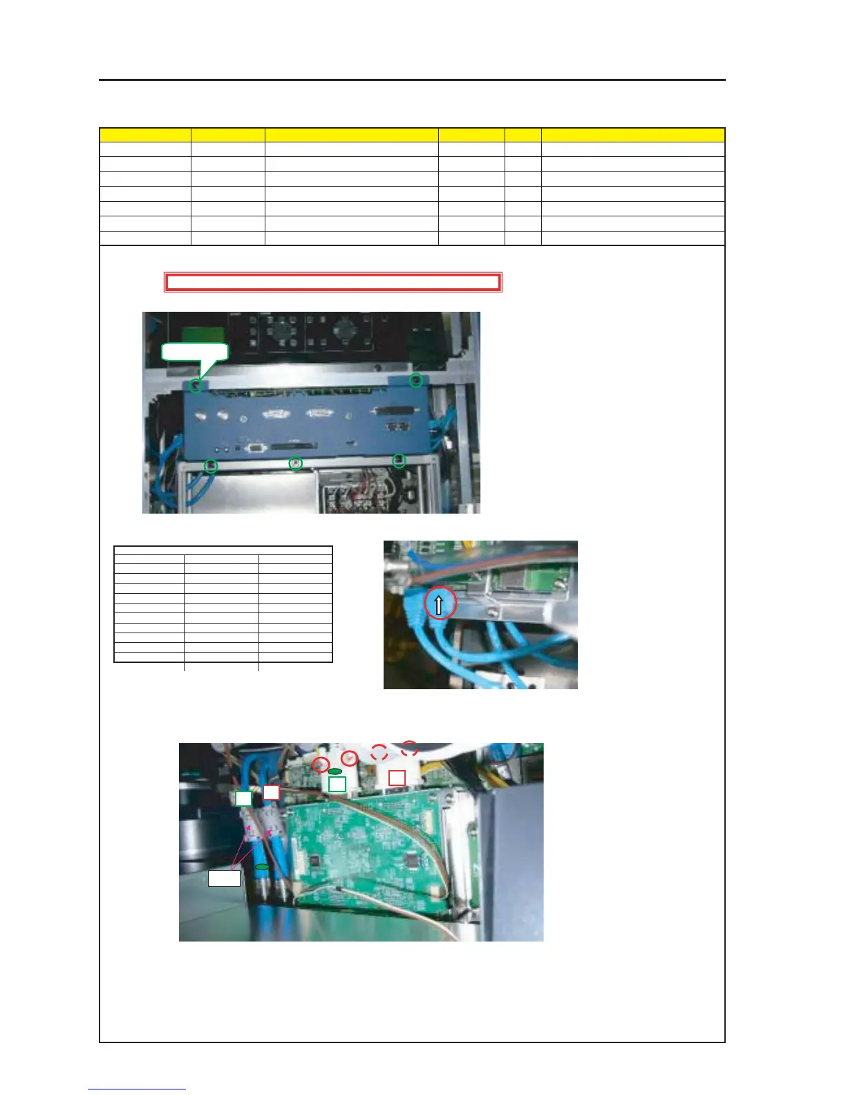
ASSEMBLY DIAGRAM
Diagram symbol Circuit symbol Part name Part code Q’ty Remarks
SRW013 PL-CPIMS*4*10*3KF 24V00461 5 Torque check
GLUE,SCREW LOCK 92201082 Adequate quantity
PRT1 CORE E04SR200932 6N160006 2
MT CPU’S
1 When all parts have been assembled in the Bracket (ARM), mount the assembly on the set.
2 Make connector connections.
4 Insert the SDI (A)(B) and the DVI (A)(B), extended from the MOTHER PWB ASSY.
After screw tightening, apply a screw lock agent to the DVI (4 positions in all).
* A green marking is provided to the Terminal A side of the DVI cable and the SDI from the Mother PWB Assy.
Make sure not to make a mistake by wrong insertion.
3 Connect the LAN Cable of the MOTHER PWB to the ETHER PWB (M8507).
CT CPU MOTHER
GPIO GPIO MOTHER
N8 MOTHER CPU
CI CPU PED-A
DO PJ-DIV DVIOUT
PU PJ-DIV RELAY
LAN PJ-DIV ETHER
PD PJ-DIV MOTOR
CF PJ-DIV CPU
CP PJ-DIV CPU
Connector Connect to Connect from
CE PJ-DIV CPU
A
A
B
B
SPW013 X 5
Caution : External parts shall be handled carefully so that they are not damaged.
PRT1