9-77
“Confidential, Do Not Duplicate without written authorization from NEC.”
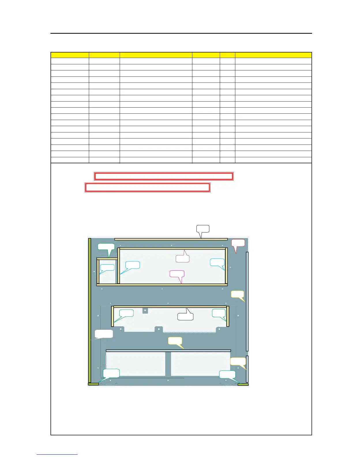
ASSEMBLY DIAGRAM
Side Panel LF Sassy
Diagram symbol Circuit symbol Part name Part code Q’ty Remarks
PRT1 SIDE PANEL LF ASSY 24PS5271 1
PRT2 GASKET(STG0.5-8) 24C07561 2 330mm
PRT3 GASKET(STG0.5-8) 24C07561 1 310mm
PRT4 GASKET(STG0.5-8) 24C07561 1 380mm
PRT5 GASKET(STG0.5-8) 24C07561 1 70mm
PRT6 GASKET(STG0.5-8) 24C07561 2 100mm
PRT7 GASKET(STG0.5-8) 24C07561 3 60mm
PRT8 GASKET(STG1-7) 24C05331 1 360mm
PRT9 GASKET(STG1-7) 24C05331 1 250mm
PRT10 GASKET(STG1-7) 24C05331 1 100mm
PRT11 GASKET(STG2-10) 24C06051 1 410mm
PRT12 GASKET(STG2-10) 24C06051 2 40mm
1 Cut the Gasket (STG0.5-8) into pieces of 380mm, 330mm, 310mm, 100mm, 70mm, and 60mm respectively
and stick them to the Shield Panel LF Assy.
2 Cut the Gasket (STG1-7) into pieces of 360mm, 250mm, and 100mm respectively and stick them to the
Side Panel LF Assy.
3 Cut the Gasket (STG2-10) into pieces of 410mm and 40mm respectively and stick them to the Side Panel LF Assy.
PRT2
PRT2
PRT3
PRT4
PRT7
PRT5
PRT6
PRT6
PRT7
PRT7
PRT8
PRT9
PRT10
PRT12
PRT12
PRT111
PRT1
Caution : External parts shall be handled carefully so that they are not damaged.
Caution : EMI (Electromagnetic Interference: Radio interference noise)