9-76
“Confidential, Do Not Duplicate without written authorization from NEC.”
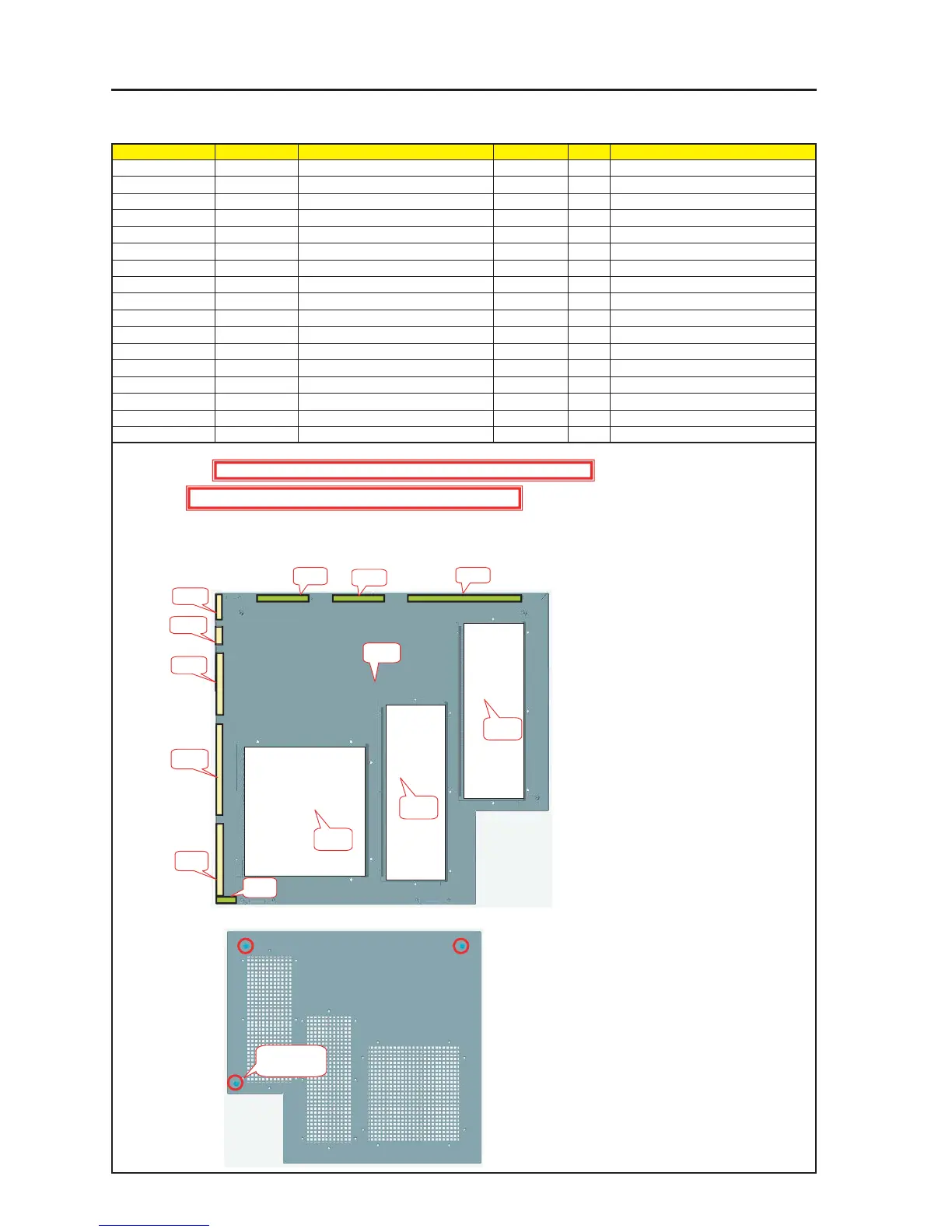
ASSEMBLY DIAGRAM
Diagram symbol Circuit symbol Part name Part code Q’ty Remarks
PRT1 SIDE PANEL RF ASSY 24PS5291 1
PRT2 GASKET(STG1-7) 24C05331 1 40mm
PRT3 GASKET(STG1-7) 24C05331 1 20mm
PRT4 GASKET(STG1-7) 24C05331 1 80mm
PRT5 GASKET(STG1-7) 24C05331 1 120mm
PRT6 GASKET(STG1-7) 24C05331 1 100mm
PRT7 GASKET(STG2-10) 24C06051 2 70mm
PRT8 GASKET(STG2-10) 24C06051 1 170mm
PRT9 GASKET(STG2-10) 24C06051 1 40mm
PRT10 FILTER B 24J28391 2 170mm
PRT11 FILTER A 24J28381 1 40mm
PRT12 SPECIAL SCREW(M4*18) 24N08431 3
PRT13 PIWA*4*3GF 24V00661 3
Side Panel RF Sassy
1 Cut the Gasket (STG1-7) into pieces of 20mm, 40mm, 80mm, and 100mm respectively and stick them to the Side Panel RF Assy.
2 Cut the Gasket (STG2-10) into pieces of 40mm, 70mm, and 170mm respectively and stick them to the Side Panel RF Assy.
3 In the location where the gaskets have been attached to the Side Panel RF Assy, install the Filter A and Filter B.
4 After the PIWA*4*3GF has been installed on the Side Panel RF Assy, mount the SPECIAL SCREW (M4*18).
PRT1
PRT2
PRT3
PRT4
PRT5
PRT6
PRT9
PRT7
PRT7
PRT8
PRT10
PRT10
PRT11
PRT12 X 3P
PRT13 X 3P
Caution : External parts shall be handled carefully so that they are not damaged.
Caution : EMI (Electromagnetic Interference: Radio interference noise)