9-78
“Confidential, Do Not Duplicate without written authorization from NEC.”
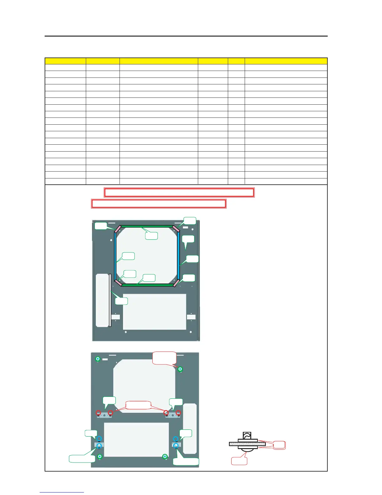
ASSEMBLY DIAGRAM
Diagram symbol Circuit symbol Part name Part code Q’ty Remarks
PRT1 FRONT PANEL B ASSY 24PS4042 1
PRT2 GASKET(STG7-10) 24C08591 1 190mm
PRT3 BRACKET(FD)ASSY 24HS4011 2
SRW301 SCREW,PL-CPIMS*3*8*3GF 24V00111 4 Torque check
PRT4 BRACKET(FF)ASSY 24HS4041 2
SRW302 SCREW,PL-CPIMS*3*8*3GF 24V00111 4 Torque check
PRT5 SRW122 WASHER(TM-137-2) 24C08391 8
PRT6 SRW106 SCR(TL-243-2) 24N08071 4
PRT7 GASKET(STG0.5-8) 24C07561 2 200mm
PRT8 GASKET(STG0.5-8) 24C07561 2 180mm
PRT9 GASKET(STG0.5-8) 24C07561 4 25mm
Front Panel B Sassy
1 Cut the Gasket (STG0.5-8) into a piece of 190mm and stick it to the Front Panel B Assy.
2 When the Washer (Tm-137-2) is attached with the SCR (TL-243-2), mount this SCR on the Front Panel B Assy.
PRT1
PRT2
PRT3
PRT4
PRT4
PRT3
SRW301 X 2
SRW301 X 2
SRW301 X 2
PRT5 X 8P
PRT6 X 4P
PRT6
Caution : External parts shall be handled carefully so that they are not damaged.
Caution : EMI (Electromagnetic Interference: Radio interference noise)
PR7
PRT7
PRT8
PRT8
PRT9
PRT9
PRT9
PRT9
PRT5