9-81
“Confidential, Do Not Duplicate without written authorization from NEC.”
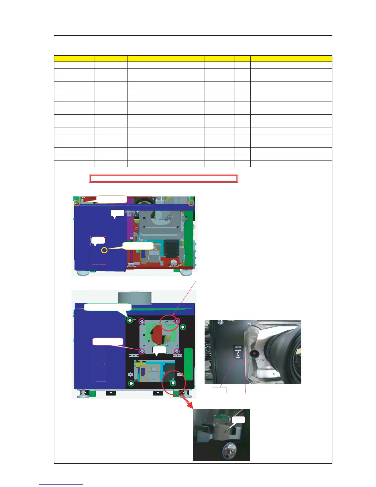
ASSEMBLY DIAGRAM
MT Front A & B
Diagram symbol Circuit symbol Part name Part code Q’ty Remarks
PRT1 Front Panel A Sassy 82N94211 1
SRW096 PL-CPIMS*4*10*3KF 24V00461 2 Torque check
PRT2 FRONT PANEL F 24P04471 1
SRW090 SCREW,PL-CPIMS*3*8*3GF 24V00111 1 Torque check
PRT3 Front Panel B Sassy 82N94221 1
4 Lockup shall be carried out.
SRW025 SCREW,PL-CPIMS*3*8*3GF 24V00111 4 Torque check
PRT4 GASKET(STG7-10) 24C08591 2 10mm
PRT5 LABEL(LENS LOCK) 24L64421 1
1 Install the Front Panel A Sassy.
After the installation, make key locking.
2 Install the Front Plate F Sassy.
5 Cut the Gasket (STG7-10) into a piece of 10mm and stick it to the
Front Panel B Sassy.
Caution : The Gasket (PRT4) shall not override the Front Panel B.
PRT1
PRT2
SRW096 X 2P
SRW090 X 1P
Accessory screw X 1P
SRW096 X 2P
PRT3
Caution : External parts shall be handled carefully so that they are not damaged.
PRT4
Position 10mm from the edge
PRT5
3 Put conductive cloth in the holder.
4 According to the lock lever of the lens mount, stick the center part
of the LABEL (LENS LOCK) to a place about 10mm from the edge
of the Front Panel B Sassy.