9-84
“Confidential, Do Not Duplicate without written authorization from NEC.”
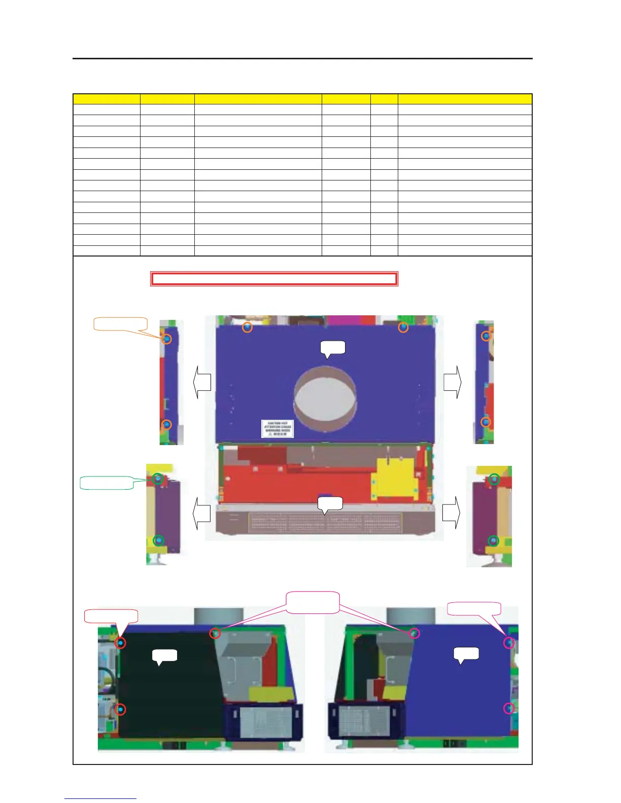
ASSEMBLY DIAGRAM
Diagram symbol Circuit symbol Part name Part code Q’ty Remarks
PRT1 Top Panel R Sassy 82N94311 1
SRW098 PL-CPIMS*4*10*3KF 24V00461 6
PRT2 REAR PANEL B SASSY 82N94331 1
SRW107 PL-CPIMS*4*10*3KF 24V00461 4
PRT3 Side Panel RR Sassy 82N94291 1
SRW103 PL-CPIMS*4*10*3KF 24V00461 3
PRT4 Side Panel LR Sassy 24PS5281 1
SRW101 PL-CPIMS*4*10*3KF 24V00461 3
MT Side & Rear
Install the external parts.
1 Install the Top Panel R Sassy and the Rear Panel B Sassy.
2 Install the Side Panel RR Sassy and the Side Panel LR Sassy.
PRT1
PRT2
SRW098 X 6P
SRW104 X 4P
PRT3
PRT4
SRW103 X 3P
Caution : External parts shall be handled carefully so that they are not damaged.
SRW101 X 3P
This screw shall
be fixed first.