9-85
“Confidential, Do Not Duplicate without written authorization from NEC.”
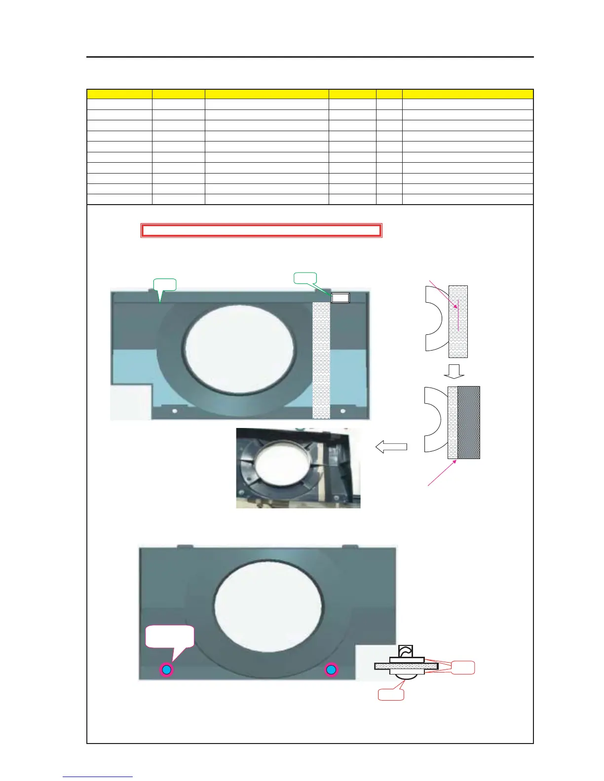
ASSEMBLY DIAGRAM
Front Panel C Sassy
Diagram symbol Circuit symbol Part name Part code Q’ty Remarks
PRT1 FRONT PANEL C 24D14151 1
PRT2 CUSHION(30*18*T5) 24J30881 1
PRT3 SRW106 SCR(TL-243-2) 24N08071 2
PRT4 SRW122 WASHER(TM-137-2) 24C08391 2
PRT5 CONDUCTIVE CLOTH TAPE 9R030011 1 L=230mm
PRT6 ACETATE CLOTH TAPE 9R030010 1 L=230mm
1 Stick the Cushion (30*18*T5) to the Front Panel C.
(This cushion is intended to press the Tamp SW.)
PRT3
PRT4
PRT4 X 4P
PRT3 X 2P
Caution : External parts shall be handled carefully so that they are not damaged.
PRT1
PRT2
2 Adjust and stick the center part of the
CONDUCTIVE CLOTH TAPE to the
circular end of the Front Panel C.
3 Adjust and stick the edge part of the
ACERATE CLOTH TAPE approximately
to the center part of the CONDUCTIVE
CLOTH TAPE.
4 When the Washer (Tm-137-2) is attached with the SCR (TL-243-2), mount this SCR on the Front Panel C.