9-86
“Confidential, Do Not Duplicate without written authorization from NEC.”
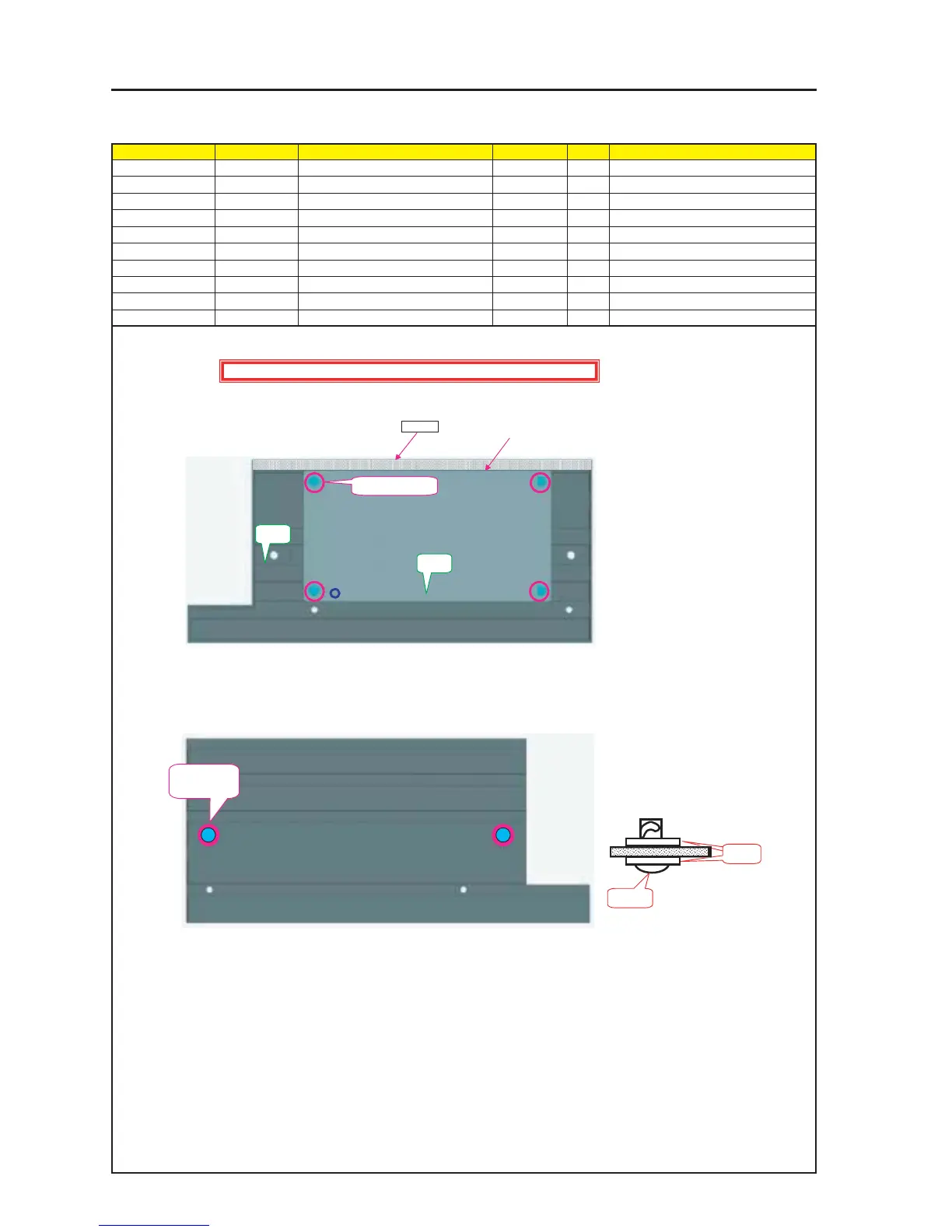
ASSEMBLY DIAGRAM
Diagram symbol Circuit symbol Part name Part code Q’ty Remarks
PRT1 FRONT PANEL D 24D14161 1
PRT2 SHIELD PLATE(FRONT) 24H56652 1
SRW024 Pl-CPIMS*4*10*3KF 24V00461 4
PRT3 SCR(TL-243-2) 24N08071 2
PRT4 WASHER(TM-137-2) 24C08391 2
PRT5 GASKET(STG8-10) 24C05341 1 L=325mm
Front Panel D Sassy
1 Install the Shield Plate (Front) on the Front Panel D Assy.
3 When the Washer (Tm-137-2) is attached with the SCR (TL-243-2), mount this SCR on the Front Panel D Assy.
PRT1
SRW024 X 4P
PRT2
PRT4
PRT3
PRT3 X 4P
PRT4 X 2P
Caution : External parts shall be handled carefully so that they are not damaged.
PRT5
2 Secure a close contact with the SHIELD PLATE (FRONT)
and stick the GASKET (STG8-10) to this shield plate.