9-88
“Confidential, Do Not Duplicate without written authorization from NEC.”
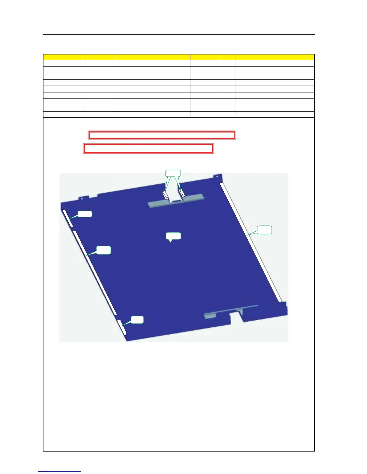
ASSEMBLY DIAGRAM
Top Panel F Sassy
Diagram symbol Circuit symbol Part name Part code Q’ty Remarks
PRT1 TOP COVER F ASSY 24PS5251 1
PRT2 GASKET(STG0.5-8) 24C07561 2 80mm
PRT3 GASKET(STG0.5-8) 24C07561 1 480mm
PRT4 GASKET(STG7-10) 24C08591 2 30mm
PRT5 GASKET(STG0.5-8) 24C07561 1 680mm
PRT2
PRT1
PRT6
PRT4
PRT3
PRT2
PRT5
1 Cut the Gasket (STG0.5-8) into the respective lengths of 80mm and 480mm, and stick them to the Top Cover F Assy.
2 Cut the Gasket (STG7-10) into a length of 30mm and stick it to the Top Cover F Assy.
Caution : External parts shall be handled carefully so that they are not damaged.
Caution : EMI (Electromagnetic Interference: Radio interference noise)