9-89
“Confidential, Do Not Duplicate without written authorization from NEC.”
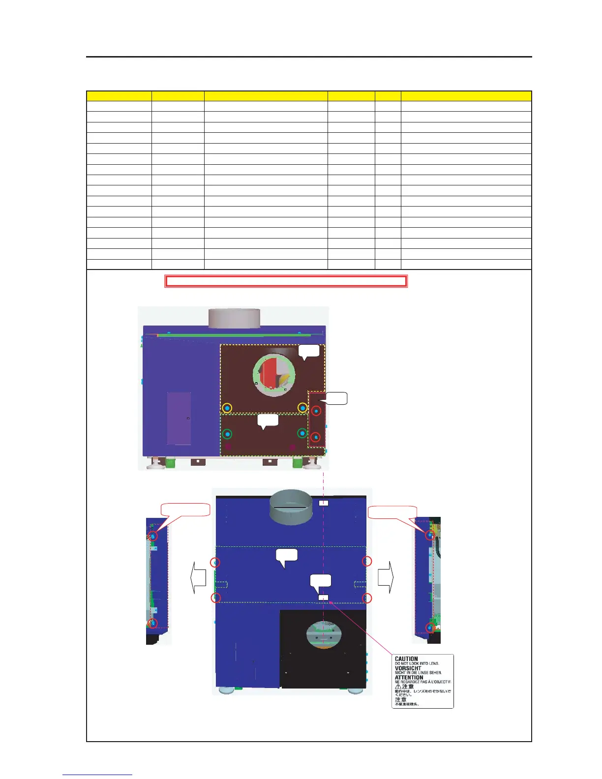
ASSEMBLY DIAGRAM
Diagram symbol Circuit symbol Part name Part code Q’ty Remarks
PRT1 Front Panel C Sassy 82N94231 1
2 Lockup shall be carried out.
PRT2 Front Panel D Sassy 82N94241 1
2 Lockup shall be carried out.
PRT3 Front Panel E Sassy 82N94251 1
2Torque check
PRT4 Top Panel F Sassy 82N94301 1
SRW097 PL-CPIMS*4*10*3KF 24V00461 4 Torque check
PRT5 CAUTION LABEL(LENS 4) 24L62581
MT Front CDE & Top F
PRT1
PRT2
PRT3
PRT4
SRW097 X 2P
SRW097 X 2P
PRT5
1 Install the Front Panel C Sassy.
After the installation, fix it with accessory screws.
2 Install the Side Panel RF Sassy and the Side Panel LF Sassy.
Caution : External parts shall be handled carefully so that they are not damaged.
* Stick the CAUTION LABEL (LENS 4) to the center of
the lens, in the position 10mm from the edge of the
Top Panel F Sassy.
In the direction where characters can be read correctly
from the lens side