9-90
“Confidential, Do Not Duplicate without written authorization from NEC.”
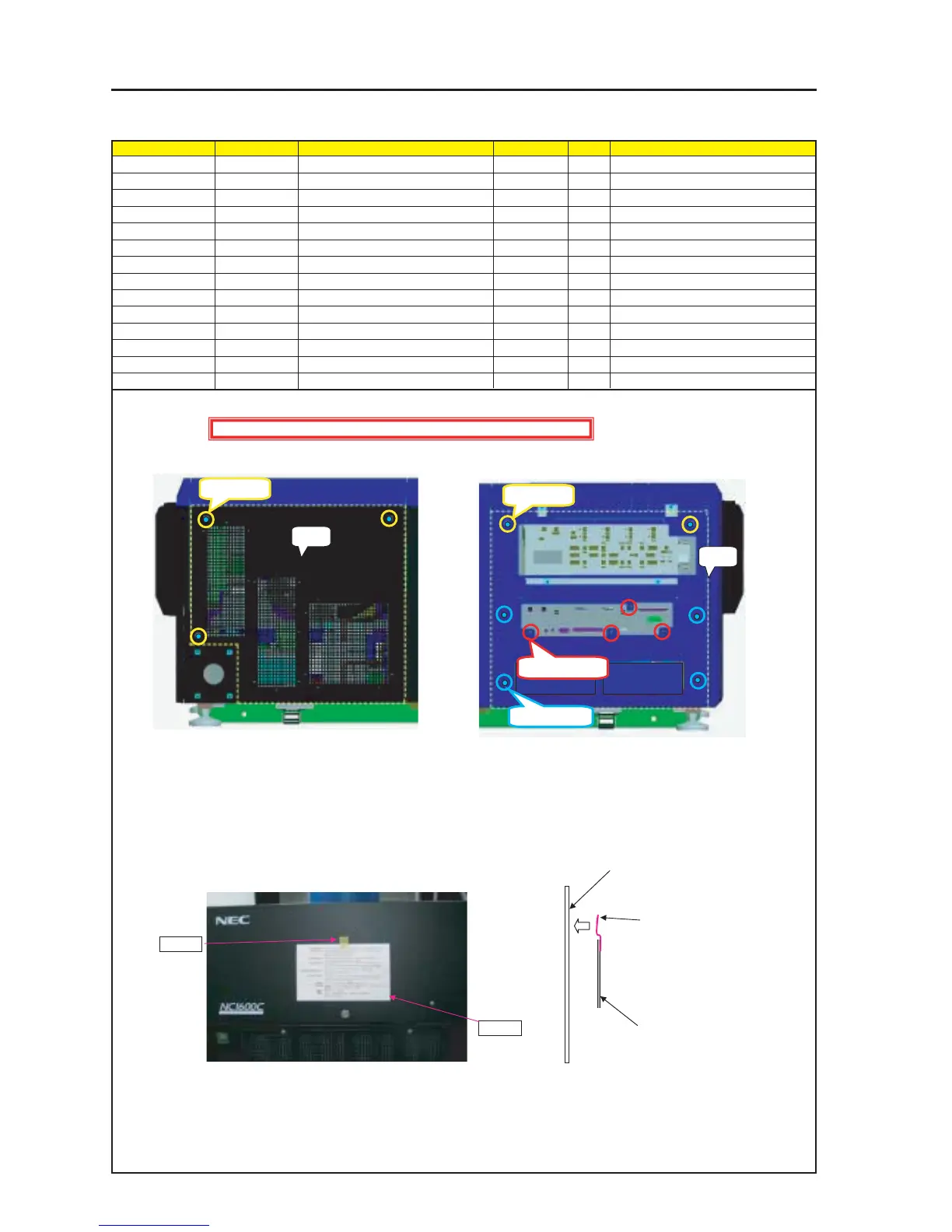
ASSEMBLY DIAGRAM
MT Rear RF & LF
Diagram symbol Circuit symbol Part name Part code Q’ty Remarks
PRT1 Side Panel RF Sassy 82N94281 1
PRT2 SPECIAL SCREW(M4*18) 24N08431 3 Torque check
1
PRT3 Side Panel LF Sassy 82N94261 1
PRT4 SPECIAL SCREW(M4*18) 24N08431 2 Torque check
SRW100 SCREW,PL-CPIMS*3*8*3GF 24V00111 4
SRW301 PL-CPIMS*4*10*3KF 24V00461 4 Torque check
PRT5 CAUTION LABEL(LAMP MAINTE) 24L63951 1
PRT6 92203051 L=40mm
PRT1
PRT3
PRT2 X 3P
PRT4 X 2P
SRW100 X 4P
SRW301 X 4P
PRT6
PRT6
CAUTION LABEL(LAMP MAINTE)
REAR PANEL A ASSY
Stick the tape after the tip of a
SCOTCH TAPE has been folded
back by about 10mm (overlapped).
1 Install the Side Panel RF Sassy and the Side Panel LF Sassy.
2 Before installing the Side Panel LF Sassy, peel off the
protection sheet from the ornamental plate (KEY).
3 Stick the CAUTION LABEL (LAMP MAINTE) to the center part of the
Rear Panel A Assy by means of a SCOTC TAPE or the like.
The TAPE shall not overlap the characters.
The tip of the tape shall be folded back by approximately 10mm.
Caution : External parts shall be handled carefully so that they are not damaged.