9-92
“Confidential, Do Not Duplicate without written authorization from NEC.”
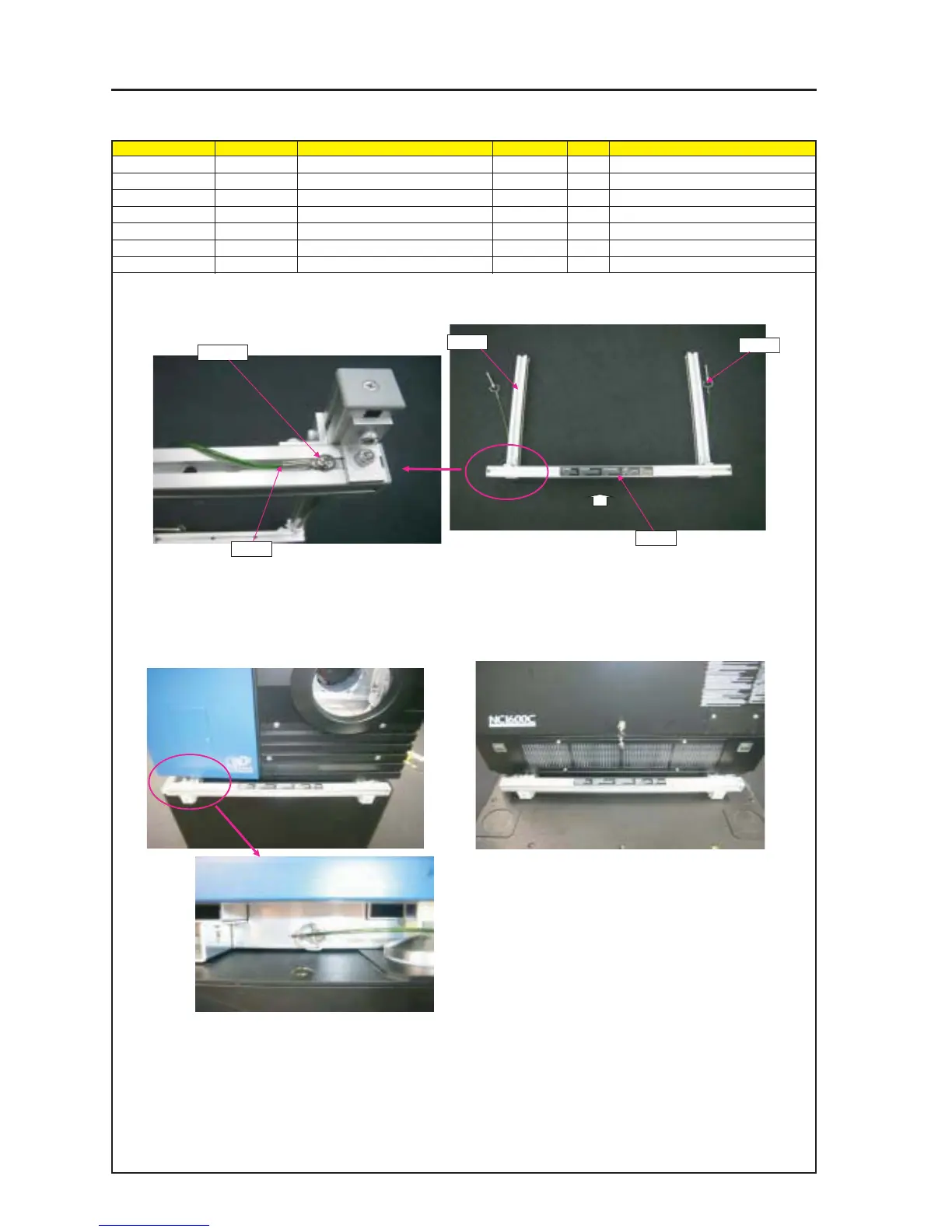
ASSEMBLY DIAGRAM
HANDLE
Diagram symbol Circuit symbol Part name Part code Q’ty Remarks
PRT1 HANDLE 24BS7841 2
PRT2 BALL LOCK PIN(BJ775-08040 24C08871 4
SRW094 PL-CPIMS*4*10*3KF 24V00461 4 Torque check
PRT3 CAUTION LABEL(HANDLE) 24L63911 2
PRT1
PRT2
PRT2
PRT3
SRW094
1 Attach the CAUTION LABEL (HANDLE) and the ball lock pin to the HANDLE.
4 Install the HANDLE on the set main body.
(When the handle has been inserted fully, insert the BALL LOCK PIN
from the side so that the handle cannot be drawn out.)
2 The BALL LOCK PIN shall be mounted so that it stands
upright along the HANDLE.
(To be mounted on both sides)
3 The CAUTION LABEL shall be stuck so that it is
positioned in the center of the HANDLE.
Direction for adhesion shall be such that the label
is legible from the direction of the arrow.
5 Insert the BALL LOCK PIN so that the HANDLE cannot be drawn out.