Home
New Rock Technologies
Gateway
MX60E
Page 19 (Figure 1-2 MX8 A Front Panel)
New Rock Technologies MX60E - Figure 1-2 MX8 A Front Panel; Figure 1-3 MX8 A Back Panel; Table 1-7 Voice Interface Cards Supported by the MX8 A; Table 1-8 Description of MX8 A Front Panel
129 pages
Manual
Save Page as PDF
To Next Page
To Next Page
To Previous Page
To Previous Page
Loading...
MX Series V
oice Gateway
User Manual
Ne
w Rock T
ec
hnologies, Inc.
19
Table 1-7
Voice Interface Cards Supported by the MX8A
Voice Interface Card Types
Number of FXS Ports
Number of FXO Ports
401A
-4FXS
4
0
401A
-4FXO
0
4
401A
-2FXS/2FXO
2
2
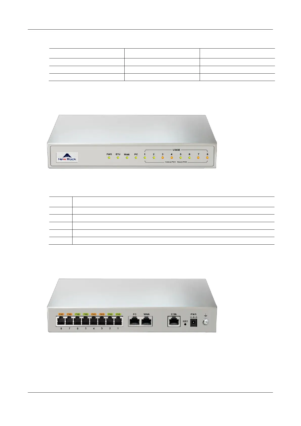
Figure 1-2
MX8A Front Panel
Table 1-8
Description of MX8A Front Panel
Item
Description
PWR
Power indicator
STU
Status indicator
WAN
WAN interface indicator
PC
PC
interface indicator
VOICE
FXS/FXO port indicator
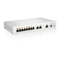
Figure 1-3
MX8A Back Panel
18
20
Table of Contents
Main Page
Amendment Records
2
Contents
3
Table of Contents
3
Figures
7
Tables
10
1 Overview
14
Product Introduction
14
Table 1-1 MX Series Gateway Hardware Specifications
14
Functions and Features
15
Equipment Structure
16
Hx4E
16
Table 1-2 Configuration Combination of HX4E
16
Figure 1-0 HX4E Front Panel
17
Figure 1-1 HX4E Back Panel
17
Table 1-3 Description of HX4E Front Panel
17
Table 1-4 Description of HX4E Back Panel
17
Mx8A
18
Table 1-5 Indicator Status of HX4E
18
Table 1-6 Configuration Combination of MX8A
18
Figure 1-2 MX8A Front Panel
19
Figure 1-3 MX8A Back Panel
19
Table 1-7 Voice Interface Cards Supported by the MX8A
19
Table 1-8 Description of MX8A Front Panel
19
Figure 1-4 RJ45 to RS232 Serial Cable
20
Figure 1-5 USB to RS232 Converter Cable
20
Table 1-9 Description of MX8A Back Panel
20
Table 1-10 Indicator Status of MX8A
20
Mx60
21
Table 1-11 Configuration Combination of MX60
21
Figure 1-6 MX60 Front Panel
22
Table 1-12 Description of MX60 Front Panel
22
Table 1-13 Pin Specifications for MX60 RJ45 Socket Port
22
Figure 1-7 Schematic Diagram of MX60 Subscriber Line Connection
23
Figure 1-8 MX60 Back Panel-AC
23
Figure 1-9 MX60 Back Panel-DC
23
Table 1-14 Description of MX60 Back Panel
23
Mx60E
24
Table 1-15 Meanings of MX60 Indicators
24
Table 1-16 Configuration Combination of MX60E
24
Figure 1-10 MX60E Front Panel
25
Table 1-17 Description of MX60E Front Panel
25
Table 1-18 Pin Specifications for MX60E RJ45 Socket Port
25
Figure 1-11 Schematic Diagram of MX60E Subscriber Line Connection
26
Figure 1-12 MX60E Back Panel-AC
26
Table 1-19 Description of MX60E Back Panel
26
Mx120G
27
Table 1-20 Meanings of MX60E Indicators
27
Table 1-21 MX60E System Operation Status
27
Table 1-22 MX120G Interface Card
27
Figure 1-13 MX120G Front Panel
28
Table 1-23 Configuration Combination of MX120G
28
Table 1-24 Description of MX120G Front Panel
28
Table 1-25 Pin Specifications for MX120G RJ45 Socket Port
28
Figure 1-14 Schematic Diagram of MX120G Subscriber Line Connection
29
Table 1-26 Corresponding Relation between MX120G RJ45 Socket and Line Number
29
Figure 1-15 MX120G Back Panel-AC
30
Figure 1-16 MX120G Back Panel-DC
30
Table 1-27 MX120G Back Panel
30
Table 1-28 Meanings of MX120G Indicators
31
Table 1-29 Mx120Gsystem Operation State
31
Web Management Page
32
Layout
32
Buttons Used on Gateway Management Interface
32
Figure 1-17 Web GUI
32
Table 1-30 Web GUI Layout Description
32
2 Parameters Setting
33
Login
33
Obtaining Gateway IP Address
33
Logging on to Web GUI
33
Table 2-1 Default IP Address of Gateway
33
Gateway Administrator and Operator Rights (Web GUI)
34
Figure 2-18 Login Interface for MX8A Gateway Configuration
34
Table 2-2 Default Passwords for Logging to Web GUI
34
Accessing through SSH
35
SSH User Permissions
36
Basic Configuration
36
Status
36
Network
36
Figure 2-19 Status Interface
36
Figure 2-20 Network Configuration Interface (HX4E/MX8A)
37
Figure 2-21 Network Configuration Interface (MX60/MX60E/MX120G)
37
Table 2-3 Network Configuration Parameters
37
Vlan
38
Figure 2-22 VLAN Configuration Interface
39
Table 2-4 VLAN Configuration Parameters
39
System
40
Figure 2-23 System Configuration Interface
41
Table 2-5 System Configuration Parameters
41
Sip
42
Table 2-6 Codec Methods Supported by Gateways
42
Figure 2-24 SIP Configuration Interface
43
Table 2-7 SIP Configuration Parameters
43
High Availability
44
Figure 2-25 High Availability Configuration Interface
44
Table 2-8 Parameters
44
Tls&Srtp
45
Figure 2-26 TLS&SRTP Configuration Interface
45
Mgcp
46
Figure 2-27 MGCP Configuration Interface
46
Table 2-9 TLS&SRTP Configuration Parameter
46
Table 2-10 MGCP Configuration Parameters
47
Foip
48
Figure 2-28 Fax Configuration Interface (HX4E/MX8A)
48
Figure 2-29 MX60/MX60E/MX120G Fax Configuration Interface
49
Table 2-11 Fax Configuration Parameters
49
Alarm
50
Table 2-12 Alarm Type
50
Figure 2-30 Alarm Icon
51
Figure 2-31 Alarms Interface
51
Line
52
Phone Number
52
Subscriber Line Features
52
Figure 2-32 Configuration Interface for Batch Configuration (Phone Number)
52
Table 2-13 Configuration Parameters of Batch Configuration (Phone Number)
52
Figure 2-33 Subscriber Line Configuration Interface
53
Table 2-14 Subscriber Line Configuration Parameters
53
Subscriber Line Batch (Unavailable on the HX4E)
55
Subscriber Line Characteristics
56
Figure 2-34 Feature Batch Configuration Interface
56
Figure 2-35 Subscriber Line Characteristics Configuration Interface
57
Table 2-15 Subscriber Line Characteristics Configuration Parameter
57
Trunk
59
Phone Number
59
Figure 2-36 Phone Number Configuration Interface
59
Table 2-16 Configuration Parameters of FXO Phone Number
59
Trunk Features
60
Figure 2-37 Trunk Line Features Configuration Interface
60
Table 2-17 Configuration Parameters of Trunk Features
60
Trunk Batch (Unavailable on the HX4E)
61
Trunk Characteristics
62
Figure 2-38 Trunk Batch Configuration Interface
62
Figure 2-39 Trunk Characteristics Configuration Interface
63
Table 2-18 Trunk Characteristics Configuration Parameter
63
Routing
64
Digit Map
64
Figure 2-40 Configuration Interface for Digit Map
65
Table 2-19 Description of Digit Map
65
Routing Table
66
Figure 2-41 Routing Table Configuration Interface
67
Table 2-20 Routing Table Format
68
Table 2-21 Number Transformations
68
Table 2-22 Routing Destination
69
Examples of Routing Rules
70
Advanced Configuration
71
System
71
Figure 2-42 Interface of System Advanced Configuration
72
Table 2-23 NAT Configuration Parameters
72
Auto Provisioning
73
Figure 2-43 Interface of Auto Provisioning Configuration
73
Table 2-24 Auto Provisioning Configuration Parameters
73
Management System Type
74
Figure 2-44 SNMP Configuration Interface
74
Table 2-25 SNMP Configuration Parameters
74
Certificate (Available on the HX4E/MX8A)
75
Figure 2-45 TR069 Configuration Interface
75
Table 2-26 TR069 Configuration Parameters
75
Media Stream
76
Figure 2-46 Certificate Configuration Interface
76
Figure 2-47 HX4E/MX8A Media Stream Configuration Interface
76
Figure 2-48 MX60/MX60E/MX120G Media Stream Configuration Interface
77
Table 2-27 Media Stream Configuration Parameter
77
SIP Configuration
78
Figure 2-49 SIP Related Configuration Interface
78
Table 2-28 SIP Related Configuration Parameter
79
RADIUS (Unavailable on the HX4E)
81
Figure 2-50 RADIUS Configuration Interface
81
Greeting
82
Figure 2-51 Greeting Interface
82
Table 2-29 RADIUS Configuration Parameter
82
Call Progress Tone Plan
83
Figure 2-52 Call Progress Tone Configuration Interface
83
Table 2-30 Greeting Configuration Parameters
83
Table 2-31 Call Progress Tone Configuration Parameters
83
Feature Access Codes
84
Figure 2-53 Feature Codes Configuration Interface
85
Table 2-32 Feature Codes Configuration Parameter
85
Clock Service
87
Figure 2-54 Clock Service Interface
87
Table 2-33 Clock Service Parameters
88
Security
89
Access Security
89
Figure 2-55 Access Configuration Interface
90
Table 2-34 Access Security Setting Parameters
90
Access List
91
Figure 2-56 Access List Configuration Interface
91
Brute Force Login Prevention
93
Figure 2-57 Brute Force Login Prevention (Login Retry Lockout) Configuration Interface
93
Table 2-35 Login Retry Lockout Parameters
93
ACL-Based Traffic Filtering
94
Figure 2-58 Brute Force Login Prevention (Lockout IP Addresses) Interface
94
Figure 2-59 Static Defense Configuration Interface
94
Table 2-36 Brute Force Login Prevention (Lockout IP Addresses) Information
94
Table 2-37 Static Defense Configuration Parameters
94
Packet Rate Limiting Based Dynamic Blacklisting
95
Figure 2-60 Dynamic Defense Configuration Interface
96
Table 2-38 Dynamic Defense (Rule Configuration) Parameters
96
Figure 2-61 Dynamic Defense (Blocked IP Addresses) Interface
97
Table 2-39 Dynamic Defense (Blocked IP Addresses) Information
97
Table 2-40 Subsequent Choices for Moving the Blocked IP Addresses to Static Defense
97
IP Table
98
Voice Security
98
Figure 2-62 IP Table Configuration Interface
98
Encryption
99
Figure 2-63 Voice Security Configuration Interface
99
Figure 2-64 Encryption Configuration Interface
99
Table 2-41 Encryption Configuration Parameters
99
VPN (Available on the HX4E/MX8A)
100
Status
101
Call Status
101
Figure 2-65 VPN Configuration Interface
101
Table 2-42 VPN Configuration Parameters
101
Call History on FXS
102
Call History on FXO
102
Figure 2-66 Call Status Interface
102
Figure 2-67 Interface of Call History on FXS
102
Figure 2-68 Interface of Call on FXO
102
SIP Message Count
103
Logs
103
System Status
103
Figure 2-69 SIP Message Count Interface
103
Call Message
104
Figure 2-70 System Status Interface
104
Table 2-43 System Status Parameters
104
System Startup
105
Manage Log
105
Figure 2-71 Call Message Interface
105
Figure 2-72 Interface of System Startup
105
Figure 2-73 Manage Log Interface
106
Table 2-44 Log Management Configuration Parameters
106
Tools
107
Configuration Management
107
Figure 2-74 Log Saving Interface
107
Figure 2-75 Path Saving Interface
107
Upgrade
108
Figure 2-76 Configuration Management Interface
108
Figure 2-77 Upgrade Interface
108
Figure 2-78 Upgrading Interface by .Img File
108
Restore Factory Settings
109
Figure 2-79 Upgrade Interface
109
Figure 2-80 Restore Factory Settings Interface (HX4E/MX8A)
109
Figure 2-81 Restore Factory Settings Interface (MX60/MX60E/MX120G)
109
Capture Recordings on the Port
110
IP Capture
110
Network Diagnosis (HX4E/MX8A)
110
Figure 2-82 Interface for Capturing Port Recordings
110
Figure 2-83 Ethereal Capture Interface
110
Product Information
111
Reboot
111
Logout
111
Figure 2-84 Automatic Diagnosis Interface
111
Figure 2-85 Ping Diagnosis Interface
111
3 Appendix: VLAN Configuration
112
Automatic Discovery
112
Lldp
113
Figure 3-86 Scenario Diagram
114
Figure 3-87 Procedure of Handling LLDP Message Carrying a VLAN ID
115
Figure 3-88 Procedure of Handling the LLDP Message with no VLAN ID
115
Dhcp
116
Figure 3-89 LLDP Message
116
Figure 3-90 Adding a VLAN ID to the Message to be Sent
116
Manual Configuration
118
Single VLAN
118
Multi-Service VLAN
119
Figure 3-91 Configuring the Single VLAN
119
Figure 3-92 a Data Packet Carrying a Corresponding VLAN Tag in the Single VLAN Mode
119
Figure 3-93 Configuring Voice VLAN to Work in Mode 1
120
Figure 3-94 Configuring Voice VLAN to Work in Mode 2
121
Figure 3-95 Configuring Management VLAN
122
Figure 3-96 Network Environment
122
Figure 3-97 Configuring Multi-Service VLAN
123
Figure 3-98 IP Addresses of the Device in Multi-Service VLAN
123
Figure 3-99 SIP Data Packet Carrying VLAN Tag of the Voice VLAN in the Multi-Service VLAN Mode
124
Figure 3-100 RTP Data Packet Carrying VLAN Tag of the Voice VLAN in the Multi-Service VLAN Mode
124
Figure 3-101 RTP Data Packet Carrying VLAN Tag of the Management VLAN in the Multi-Service VLAN Mode
124
Appendix: High Availability Configuration
128
Appendix: Auto Provisioning Configuration
129
Related product manuals
New Rock Technologies MX8G
125 pages
New Rock Technologies MX120G
129 pages
New Rock Technologies MX series
129 pages
MX8A Series
94 pages
HX4E Series
94 pages
New Rock Technologies HX4E
112 pages
New Rock Technologies HX4G
125 pages