29 EDH0170FE1010 – 09/98
LDS1000 Controller for Laser Diode Sensors
For each of the parameters, a modification menu uses the following func-
tions:
(F2)Lower value.
(F3)Next highest value.
(F5)Save and Return to analog output mode.
List of parameters:
NOTE
When you exit analog output mode after modifying the integration
constant, the new value is also used to calculate the display of the
controller.
Scale factors that correspond to the combined choice of the gain and the
counter increment.
Example: using the Table.
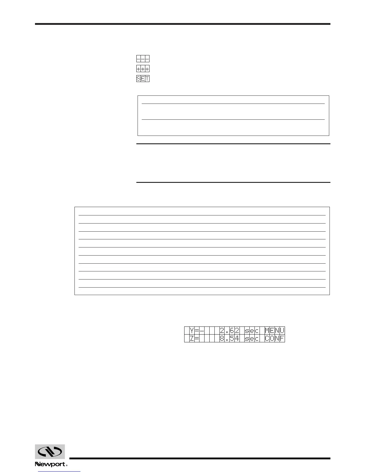
The controller operates in manual mode with a Yincr value of 0.2 and a unit
given in arc-sec. The following values can therefore be read:
We can therefore expect to obtain the following analog values:
•With a gain of 1: OUTY = - 2.62 x25 = - 65.5 mV
OUTZ = 8.54 x25 = 213.5 mV
•With a gain of 5: OUTY = -2.62 x125 mV = - 327.5 mV
OUTZ = 8.54 x125 mV = 1067.5 mV
OUTY or OUTZ in mV for a Displayed Unit (µrad, sec, …)
Incr. 0.1 0.2 0.5 1 2 5 10 20 50
Gain 1 50 mV 25 mV 10 mV 5 mV 2.5 mV 1 mV 0.5 mV0.25 mV 0.1 mV
2 100 mV 50 mV 20 mV 10 mV 5 mV 2 mV 1 mV 0.5 mV 0.2 mV
5 250 mV125 mV 50 mV 25 mV12.5 mV 5 mV 2.5 mV1.25 mV 0.5 mV
10 500 mV250 mV 100 mV 50 mV 25 mV 10 mV 5 mV 2.5 mV 1 mV
20 1 V 500 mV 200 mV100 mV 50 mV 20 mV 10 mV 5 mV 2 mV
50 2.5 V 1.25 V 500 mV250 mV125 mV 50 mV 25 mV12.5 mV 5 mV
100 5 V 2.5 V 1 V 500 mV250 mV100 mV 50 mV 25 mV 10 mV
200 10 V 5 V 2 V 1 V 500 mV200 mV100 mV 50 mV 20 mV
OUT (mV) = Measure (unit) xGain/Incr. x5
Designation Available Values Default Value
INTG Integration 0.5; 1; 2; 5; 10; 20; 100
constant (msec) 50; 100; 200; 500; 1000
GAIN Output gain 1; 2, 5; 10; 20; 50; 1
Digital/Analog 100; 200
 Loading...


