Do you have a question about the Newport LDS1000 and is the answer not in the manual?
Describes the LDS1000 Controller and its capabilities, including displaying angular variations and storing measurements.
Lists the items included with the LDS1000 electronic controller and the sensor.
Details the different operating modes, including manual, remote, and analog modes.
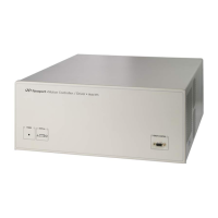
Lists the different versions of the LDS1000 Controller based on options.
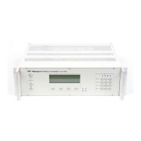
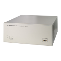
Provides the physical dimensions and connector layout of the LDS1000 Controller.
Explains the technology behind the NEWPORT LDS series sensors and their signal reception.
Details the functions performed by the LDS1000 Controller, its processing capabilities, and interfaces.
Lists the general specifications for both the LDS-Vector Optical Head and the LDS1000 Controller.
Specifies the operating temperature and humidity limits for the LDS1000 Controller.
Details the baud rate and mode parameters for RS-232-C and IEEE-488 interfaces.
Lists the electrical characteristics and limitations of the analog outputs.
Explains the calibration certificate and parameters required for configuring the LDS1000 Controller.
Describes how the controller performs noise reduction techniques for measurements.
Explains how to adjust electronic offset coefficients for the detector.
Guides on setting up the sensor, referring to individual sensor manuals.
Emphasizes the importance of solid mounting for accurate small movement measurements.
Provides instructions and cautions for making electrical connections, including cable usage.
Explains the power-up sequence, initialization, and welcome messages displayed by the controller.
Lists and explains various messages that can be displayed during the controller's power-up sequence.
Guides on ensuring proper alignment for visualizing angular measurements.
Details how to configure the controller with different sensors and store their parameters.
Explains how to choose communication modes and parameters for connecting to a computer.
Describes the RS-232-C protocol, connection, and default parameters.
Describes the IEEE-488 protocol, connection, and default parameters.
Covers controller configuration based on options, software version, and display brightness.
Explains how to configure analog output parameters like integration constant and gain.
Explains how to access the controller's manual mode and its starting point.
Details the functions available within the manual mode, categorized into sub-menus.
Describes specific measuring functions like Display Freeze and Offset Origin.
Explains the function of freezing the display for easier reading of measurements.
Details how to set the current point as the origin for relative measurements.
Explains the integration constant parameter and its effect on measurement accuracy.
Recommends graphic display for facilitating alignments, using a Bar-Graph representation.
Explains how to check the received light level for proper instrument setup.
Describes the maintenance mode, which displays raw analog/digital converter values.
Outlines the functions for parameter input of sensors, controller, and interfaces.
Describes how to display and access current sensor parameters for modification.
Explains how to modify the number of the currently active sensor.
Details how to modify sensor parameters like S/N, Type, Ycoef, Yincr, etc.
Explains how to display results in arc-seconds and correct parameters for this mode.
Guides on programming a new sensor into the controller's memory.
Explains how to check if the current sensor matches the connected one and view its parameters.
Details how to access and modify communication parameters for RS-232-C and IEEE-488.
Explains how to adjust the display brightness of the controller.
Describes how to read the installed memory size for acquisitions.
Explains how to check if the analog output option is present on the controller.
Explains how to select analog outputs and the parameters that can be configured.
Details how to modify integration constant (INTG) and gain (GAIN) for analog outputs.
Explains the conventions for logical inputs (TRIG) and outputs (PWOK).
Details the specifications and compatibility of the TRIG input.
Details the specifications of the PWOK output.
Guides on checking the physical connection and compatibility of interface parameters.
Describes the RS-232-C interface cable, connection, and recommended terminal program settings.
Describes the IEEE-488 interface requirements, recommended card, and default parameters.
Introduces the LDS-TOOLS software for communication and its system requirements.
Presumes interface parameters are checked and covers basic programming concepts for computer communication.
Explains the structure of ASCII messages sent to the controller and how they are processed.
Details conventions for accessing Interface Mode, axis naming, and measurement formats.
Lists commands categorized by System Management, Sensor Parameters, Acquisitions, and I/O.
Provides an alphabetical listing of all commands recognized by the controller.
Defines the integration constant parameter (INTG) for acquisitions.
Returns the controller from Interface Mode to Manual (Local) mode.
Sets the controller to Interface Mode from Manual mode.
Reads the current acquisition status via an ASCII character code.
Reads the status of the TRIG input, returning 0 or 1.
Freezes the display on "REMOTE MODE" to remove refresh response times.
Enables display in remote mode, allowing response times related to refresh.
Reads the status of the PWOK output, indicating if the sensor receives sufficient light.
Stops ongoing work and performs a system reset on the LDS1000 controller.
Sets the sample period in milliseconds for acquisition functions.
Stops ongoing acquisitions without deleting memory.
Reads the parameters of a current sensor axis (Y or Z).
Provides a description for a given error code in ASCII format.
Reads the last error code generated by the controller.
Performs measurements synchronized with an external trigger signal.
Immediately carries out a specified number of successive measurements.
Reads the number of the currently selected sensor and its series number.
Reads the current position of a specified axis (Y or Z).
Performs measurements triggered by an external signal on the TRIG input.
Reads the operational status, indicating memory type and display mode.
Reads previously saved measurements from memory.
Reads the internal program version of the controller.
Reads the currently set integration constant in milliseconds.
Reads the number of measurements currently stored in the controller's memory.
Reads the sample period currently set in milliseconds.
Provides laser safety cautions and warnings regarding the optical head.
Outlines safety precautions and maintenance procedures for the electronic controller.
Details the types of cables used for connecting sensors, computers, and other equipment.
Describes the RS-232-C cables and their pinouts for connecting to a computer.
Mentions the requirement for a standard commercial IEEE-488 cable.
Describes the sensor interface cable and its connector pin assignments.
Specifies the type of cables for analog output connectors.
Specifies the type of cable for the TRIG input connector.
Specifies the type of cable for the PWOK output connector.
Provides an example program in Quick Basic for RS-232-C communication.
Details the IEEE-488 standard and its characteristics relevant to the controller.
Lists the IEEE-488 functions supported by the LDS1000 Controller.
Describes the specific GPIB function subsets supported by the controller.
Explains the use of Serial Polling (SRQ) for obtaining information from GPIB devices.
Emphasizes the importance of proper grounding for user safety.
Cautions about connecting external equipment and cables, ensuring EC compliance.
Advises reading sensor manual and using specified cables for connection.
Provides crucial safety information regarding laser radiation and eye exposure.
Warns about dangerous voltage and risks associated with opening the equipment.
Lists safety regulations for instrument usage, including environmental conditions and modifications.
Provides guidelines for systematically disconnecting the equipment in various scenarios.
| Brand | Newport |
|---|---|
| Model | LDS1000 |
| Category | Controller |
| Language | English |