EasyManua.ls Logo

Nexo NXAMP 4X4

Nexo NXAMP 4X4
153 pages
To Next Page IconTo Next Page
Loading...
SERVICE MANUAL
Copyright (c) NEXO S.A. All rights reserved. PDF ´09.10
PA
011947
CONTENTS
(目次)
PANEL LAYOUT
(パネルレイアウト)
...........................................................3
CIRCUIT BOARD LAYOUT
(ユニットレイアウト)
........................................4
SERVICE PRECAUTIONS
(サービス時の注意)
............................................5
OVERALL ASSEMBLY WIRING
(総組立配線図)
..........................................7
DISASSEMBLY PROCEDURES
(分解手順)
...............................................25
LSI PIN DESCRIPTION
(LSI 端子機能表)
...................................................37
IC BLOCK DIAGRAM
(IC ブロック図)
.......................................................38
CIRCUIT BOARDS
(シート基板図)
.............................................................44
TEST PROGRAM .......................................................................................64
テストプログラム
........................................................................................71
INSPECTIONS ...........................................................................................78
検査
.............................................................................................................83
UPDATING THE FIRMWARE .....................................................................88
ファームウェアのアップデート
....................................................................90
PARTS LIST
BLOCK DIAGRAM
IC & DIODE FIGURES
CIRCUIT DIAGRAM

Table of Contents

Other manuals for Nexo NXAMP 4X4

Question and Answer IconNeed help?

Do you have a question about the Nexo NXAMP 4X4 and is the answer not in the manual?

Nexo NXAMP 4X4 Specifications

General IconGeneral
BrandNexo
ModelNXAMP 4X4
CategoryRecording Equipment
LanguageEnglish

Summary

General Safety and Handling Warnings

Health and Environmental Precautions

Warnings about chemical exposure and handling components.

United Kingdom Important Notice

Plug and Cord Wiring Instructions

Instructions for correctly wiring the mains plug and cord according to safety standards.

Panel Layout Overview

Front and Rear Panel Components

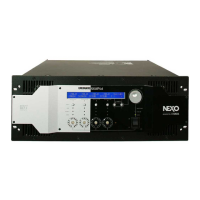
Identifies controls, indicators, and connectors on the front and rear of the unit.

Service Precautions

Safety Measures and Component Discharge

Instructions for safely handling internal components, including voltage discharge procedures.

Disassembly Procedures

Major Component Removal Steps

Steps for removing covers, circuit boards, fans, and switches.

LSI Pin Description

IC Block Diagrams

Circuit Board Identification

Test Program Overview

Required Items and Test Setup

Lists necessary hardware, software, and connection setups for performing tests.

Test Program Operation

Test Execution and Result Interpretation

Guidance on starting tests, navigating menus, and interpreting results (OK/ERROR).

Inspections

Measurement Conditions and Setup

Specifies environmental, power supply, instrument requirements, and connection diagrams for inspections.

Inspection Procedures

Mode-Specific Inspection Guidelines

Covers ordinary mode, attenuation, analog, and bridge mode inspections.

Firmware Update Procedure

Software Preparation and Update Process

Steps for downloading, installing software, and performing the firmware update.

Parts List

Overall Assembly Diagram 12

Circuit Diagram Conventions

Notation and Inter-Sheet Connector Identification

Explains symbols used in diagrams and how to identify connectors linking different sheets.

IC and Diode Figures

Wiring Diagram

Block Diagram Overview (15)

Circuit Diagrams (CONTROL Board)

Circuit Diagram (INANH Board)

Circuit Diagram (OUTANH Board)

Circuit Diagram (PN-AN Board)

Circuit Diagram (RS232-GPI Board)

Circuit Diagrams (OPT-AN, NX-DFLT Boards)

Circuit Diagram (PAANH Board)

Circuit Diagrams (PSANHAPSANHB Board - Part 1)

Circuit Diagrams (PSANHAPSANHB Board - Part 2)

Circuit Diagrams (PSANHAPSANHB Board - Part 3)