4. OUTANH シート(所要時間:約 20 分)
4-1. トップカバー、NX-DFLT カードを外します。
(1 項参照)
4-2. CONTROL シート、OPT アングルを外します。
(2 項参照)
4-3. PSANHA シートを外します。(3 項参照)
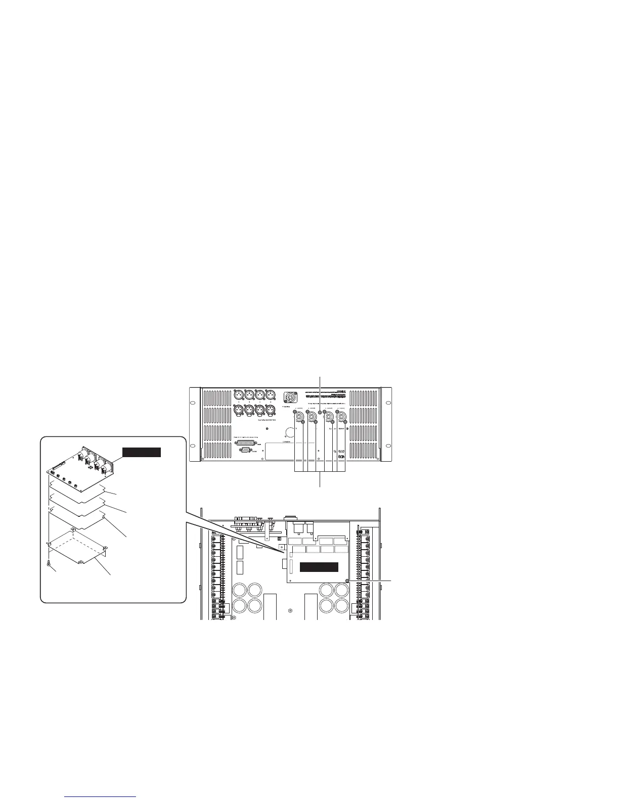
4-4. OUTANH シートから束線を外します。(図 4)
4-5. [320]のネジ 8 本、[330]のネジ 1 本、[325]のネ
ジ 1 本を外し、OUTANH シートを絶縁シート 2 枚、
シールド 2 枚と共に外します。(図 4)
4-6. [317]のプラスチックリベット3個を外し、
OUTANH シートを絶縁シート 2 枚とこれらのシート
に貼付されたシールド 2 枚から別けます。(図 4)
注: 絶縁シート 2 枚とシールド 2 枚は、両面テー
プで互いに貼り付けられているために分離す
ることはできません。
4. OUTANH Circuit Board
(Time required: about 20 minutes)
4-1. Remove the top cover and the NX-DFLT card.
(See procedure 1.)
4-2. Remove the CONTROL circuit board and the OPT
angle. (See procedure 2.)
4-3. Remove the PSANHA circuit board. (See procedure 3.)
4-4. Disconnect the connector assemblies from the
OUTANH circuit board. (Fig. 4)
4-5. Remove the eight (8) screws marked [320], the one
(1) screw marked [330] and the one (1) screw marked
[325]. The OUTANH circuit board can then be removed
together with the two (2) insulation sheets and the two
(2) shields. (Fig. 4)
4-6. Remove the three (3) plastic rivets marked [317]. The
OUTANH circuit board can be separated from the two
(2) insulation sheets and the two (2) shields attached
to them. (Fig. 4)
Note: The two (2) insulation sheets and the two (2)
shields can not be separated because they are
attached each other with both side adhesive
tapes.
[317]: PLASTIC RIVET NRP-345 (--)
プラスチックリベット
[320]: FLAT HEAD TAPPING SCREW-B 3x8 MFZN2B3 (--)
B タイト+ FLAT
[325]: BIND HEAD TAPPING SCREW-S 3x6 MFZN2W3 (--)
S タイト+ BIND
[330]: BIND HEAD TAPPING SCREW-B 3x8 MFZN2B3 (--)
B タイト+ BIND
Fig. 4
(図 4)
[320]
[325]
[317]
OUTANH
OUTANH
Insulation sheet 1
(絶縁シート 1)
Insulation sheet 2
(絶縁シート 2)
Shield 1
(シールド 1)
Shield 2
(シールド 2)
[330]
NXAMP4x4
28
 Loading...