3. Operation
3-1. Entry of the test program
While holding down the [SELECT4], [MUTE4] and [A]
buttons simultaneously, turn the power switch on. The
start up screen appears on the LCD.
Start Up Screen
Then release your fingers from the buttons.
The test program starts and the test menu screen ap-
pears on the LCD display.
Test Menu Screen
3-2. Executing the test and judgment display
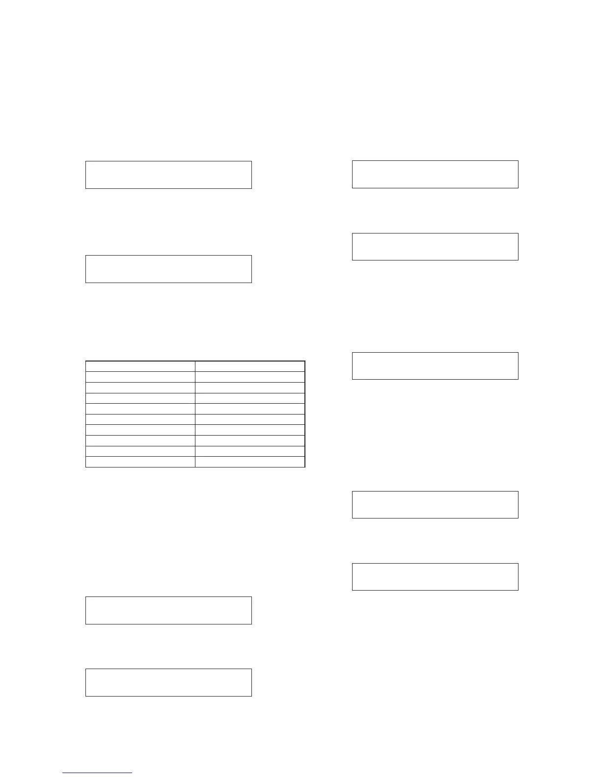
Select the desired test item from the table below using
the rotary encoder, and press the [B] button to start the
test.
Test Items List
After executing the test, the display returns to the test
menu screen if the test result is OK. If an error occurs,
“ERROR” appears on the LCD and the test program is
stopped. In that case, turn the power switch off and on
again as was done above in 3-1.
4. Outline of tests
4-1. SWITCH test
Press the [B] button to start the test. The LCD shows one
by one the switch name to be tested as shown below.
Press the switch displayed on the LCD as instructed one
by one.
If all instructed switches are OK, the display automati-
cally returns to the test menu screen.
4-2. ENCODER test
Press the [B] button to start the test. The following dis-
play appears.
Turn the ENCODER knob clockwise. The 2nd line on the
display changes as shown below.
TURN RIGHT 0 –> • • • • • –> TURN RIGHT 19
The following display appears after the 2nd line on the
display reaches TURN RIGHT 19.
Turn the ENCODER knob counterclockwise. The 2nd
line on the display changes as shown below.
TURN LEFT 0 –> • • • • • –> TURN LEFT 19
The display returns to the test menu screen after the 2nd
line on the display reaches TURN LEFT 19.
4-3. LED test
Press the [B] button to start the test. The following dis-
play appears.
The LEDs automatically light up one by one in a specific
order as shown on the next page.
All LEDs will light at the same time after each LED in-
dividually has been tested. Confirm that each LED is lit
normally. If OK, press the [B] button to return the display
to the test menu screen.
NXAMP4x4
65
00CHOOSETEST<>
01SWITCH
00CHOOSETEST<>
01SWITCH
01SWITCH
HITSELECTCH1
Boot1.29
WAIT...
00CHOOSETEST<>
02ENCODER
02ENCODER
TURNRIGHT0
02ENCODER
TURNLEFT0
00CHOOSETEST<>
03LED
03LED
01 SWITCH
02 ENCODER
03 LED
04 LCD
05 RS232
06 GPI
07 PORT (no use)
08 DSP
09 WORD CLOCK
10 12C
11 FLASH
12 FAN
13 SLOT
14 ATTENUATION
15 ANALOG
16 BRIDGE
17 CALIBRATION
18 STANDBY
19 QUIT
 Loading...