[370]
RS232-GPI
[70]
INANH
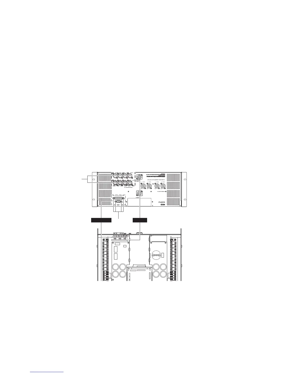
6. INANH Circuit Board
(Time required: about 7minutes)
6-1. Remove the top cover and the NX-DFLT card.
(See procedure 1.)
6-2. Disconnect the connector assembly from the INANH
circuit board. (Fig. 6)
6-3. Remove the sixteen (16) screws marked [70]. The
INANH circuit board can then be removed. (Fig. 6)
7. RS232-GPI Circuit Board
(Time required: about 7 minutes)
7-1. Remove the top cover and the NX-DFLT card.
(See procedure 1.)
7-2. Disconnect the flat cable from the RS232-GPI circuit
board. (Fig. 6)
7-3. Remove the four (4) hexagonal lock screws marked
[370]. The RS232-GPI circuit board can then be
removed. (Fig. 6)
6. INANH シート(所要時間:約 7 分)
6-1. トップカバー、NX-DFLT カードを外します。
(1 項参照)
6-2. INANH シートから束線を外します。(図 6)
6-3. [70]のネジ 16 本を外し、INANH シートを外します。
(図 6)
7. RS232-GPI シート(所要時間:約 7 分)
7-1. トップカバー、NX-DFLT カードを外します。
(1 項参照)
7-2. RS232-GPI シートからフラットケーブルを外します。
(図 6)
7-3. [370]の六角ロックネジ 4 本を外し、RS232-GPI シー
トを外します。(図 6)
[70]: BIND HEAD TAPPING SCREW-B 2.6x8 MFZN2B3 (--)
B タイト+ BIND
[370]: HEXAGONAL LOCK SCREW (--)
6 角ロックネジ
Fig. 6
(図 6)
NXAMP4x4
30
 Loading...