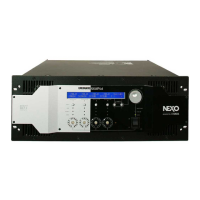
CN012
RED
(赤)
CN013
BLUE
(青)
CN014
YELLOW
(黄)
CN015
GREEN
(緑)
8. Color of the connectors connected to the
connector CN012–CN015
Connect the connector assembly from the PA unit to the
CONTROL circuit board as shown in the figure below.
(Fig. 33)
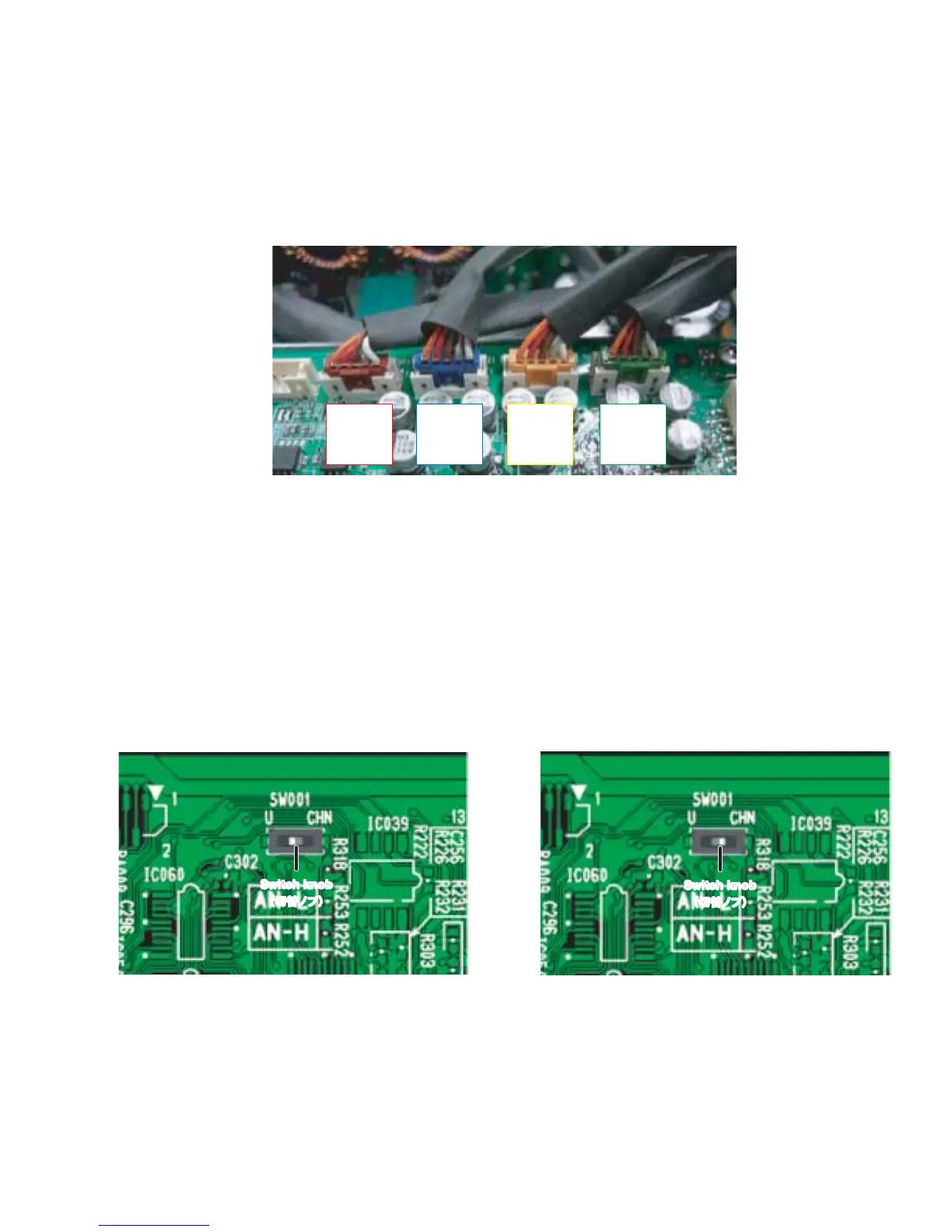
9. Change of the destination
Set the knob position of the switch SW001 on the
CONTROL circuit board as shown in the figure below.
(Fig. 34, 35)
8. CN012 − CN015 へ接続するコネクターの色
PAユニットからの束線を下図のようにCONTROLシー
トへ接続します。(図 33)
9. 仕向け先の切り替え
CONTROL シートのスイッチ(SW001)を下図のよう
に切り替えます。(図 34、35)
Fig. 33
(図 33)
Fig. 34
(図 34)
Fig. 35
(図 35)
Switch knob
(切替ノブ)
Switch knob
(切替ノブ)
U/J destination
(U / J 仕向)
CHN destination
(CHN 仕向)
NXAMP4x4
21
 Loading...