2. Wiring of the power switch
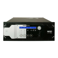
1) Install the power switch to the front panel with its
terminals set downward. (Fig. 4, 5)
2) Confirm that the power switch is set to the off position as
shown in the figure. (Fig. 6)
3) Twist the wires of the power switch assembly more than
three times.
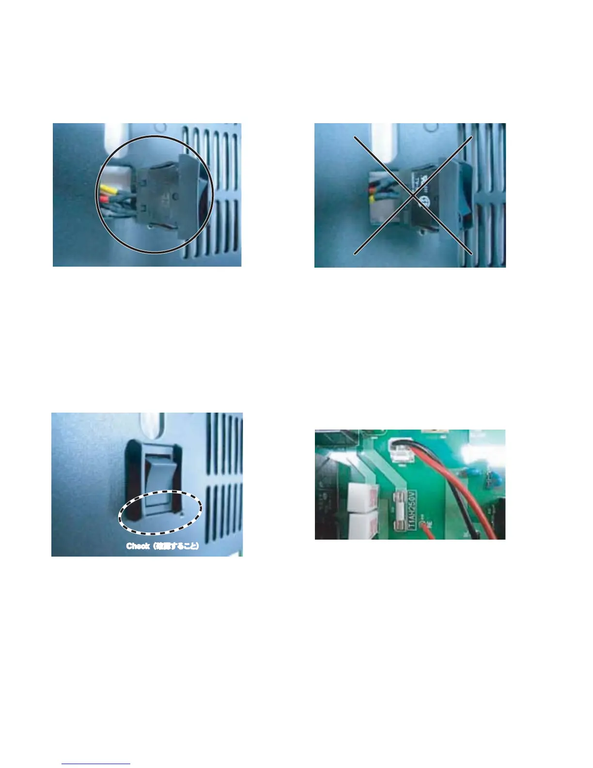
4) Connect the power switch connector assembly to the
connector (CN103) of the PSANHB circuit board. (Fig. 7)
2. 電源スイッチの配線
1) 端子の位置を下側にセットして、電源スイッチをフロ
ントパネルへ取り付けます。(図 4、5)
2) 電源スイッチが図のように OFF ポジションにセットさ
れていることを確認します。(図 6)
3) 電源スイッチの線材を 3 回以上捻ります。
4) 電源スイッチの線材を PSANHB シートのコネクター
(CN103)へ接続します。(図 7)
Fig. 4
(図 4)
Fig. 6
(図 6)
Fig. 5
(図 5)
Fig. 7
(図 7)
Check (確認すること)
NXAMP4x4
8
 Loading...