This product has various cables (wires and connector
assemblies) inside. To prevent touching component to
the cables and/or connection mistake, perform the cable
connection and fixing cables according to the following
instructions referring the wiring diagram, P3 of the circuit
diagram.
Notice: Since the following pictures are taken of the
preproduction product, they may differ from the
commodity products in detail. However, the wiring
and so on is not so differ between them. So, refer
only to wiring and so on.
1. Wiring of the PN-AN circuit board
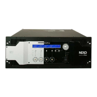
1) Process the PN FFC assembly (WR37010). (Fig. 1, 2)
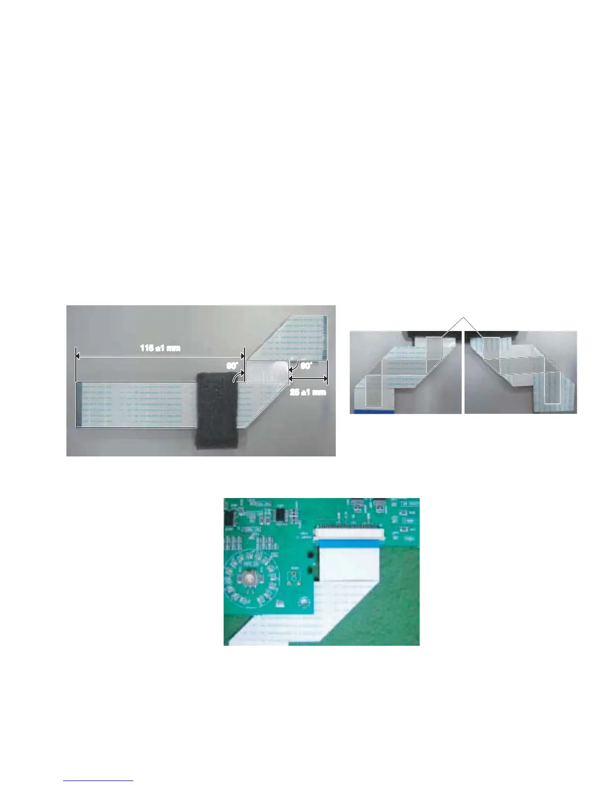
2) Connect the PN FFC assembly (WR37010) to the PN-
AN circuit board. (Fig. 3)
3) Install the PN-AN circuit board to the front panel.
本製品内部には色々な種類のケーブル(線材、束線)があり
ます。ケーブルの部品への接触やケーブルの接続ミスを防止
するために、回路図 3 ページのシート配線図を参照の上で下
記の指示にしたがってケーブルの接続と固定を行ってくださ
い。
注意: 掲載した写真は量産試作品を撮影したものですので
生産品とは細かい部分で異なりますが、配線周辺に
ついて違いはありません。配線作業用に限定して参
考にしてください。
1. PN-AN シートの配線
1) PNFFCAss'y(WR37010)を加工します。(図 1、2)
2) PNFFCAss'y(WR37010)を PN-AN シートへ接続し
ます。(図3)
3) PN-AN シートをフロントパネルへ取り付けます。
Fig. 1
(図 1)
Fig. 3
(図 3)
Fig. 2
(図 2)
■
OVERALL ASSEMBLY WIRING
(総組立配線図)
115 ±1 mm
25 ±1 mm
90˚ 90˚
[635]
Fix the bent part with adhesive tape [635].
(Attach it through the center of FFC.)
(折り曲げた部分をフィラメントテープ[635]で固定します。
(FFC の中心を通るように貼ります。))
* For details of wiring in the enclosure, refer to step “13.
Method of Fixing PN FFC Assembly”.
※ 筐体内部での配線についての詳細は「13.PN FFC
Ass'y の固定方法」を参照してください。
NXAMP4x4
7
 Loading...