--[v1.00]--
(c)NEXO2007.
-20.0-20.0-20.0-20.0Vol(dB)
[MAIN][MAIN][SUB][SUB]<>
2) Confirm that all the fans start rotation at low speed within 4 seconds after turning the power switch on.
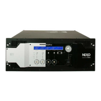
3) Confirm that the following display appears on the LCD within 18 ±3 seconds after turning the power switch on. Also
confirm that the POWER LED and only one of the VOLUME LEDs for each channel light up.
2-2. Power consumption when idling
Measure the primary power consumption and confirm that the measured value is 120 ±30 W.
2-3. Output terminal DC voltage
Measure the DC voltage (Vdc) of each output terminal and confirm that the measured value is Vdc = 0 ±50 mV.
2-4. PEAK indicator
Set this unit to GAIN: 0 dB, VOL: 0 dB.
Input the 20 kHz, 15.7 dBu, sine wave to channel 1 input terminal, and confirm that the PEAK indicator of channel 1 flashes
or lights. Input the 20 kHz, 13.2 dBu, sine wave, and confirm that the PEAK indicator of channel 1goes off.
Perform the same test for channel 2-4 in the same manner.
After test, set this unit to GAIN: 0dB, VOL: -90 dB.
3. Inspection with attenuation test mode
Condition:
• Perform each test in this section in the attenuation test mode. (See “TEST PROGRAM 4-14. ATTENUATION test”)
• Connect an 8 Ω load resistor to each output terminal.
• Ground each input terminal via a 600 Ω resistor.
3-1. Residual noise
Measure the residual noise level at each output terminal and confirm that measured value is -65 dBu or less.
Note: Measure the noise level with the 22 Hz - 22 kHz band pass filter specified at 1-3.
4. Inspection with analog test mode
Condition:
• Perform each test item in this section with the analog test mode of the test program. (See “TEST PROGRAM 4-15.
ANALOG test”)
• Unless otherwise specified, perform the test with an 8 Ω resistor connected to each output terminal.
Example of firmware version 1.00
1-5. Other
0 dBu is defined as 0.775 Vrms in these inspections.
2. Inspection with ordinary mode
Condition:
• Ground each input terminal via a 600 Ω resistance.
• Do not connect the load resistance to the output terminal.
2-1. Power ON sequence
1) Turn the power switch on. Confirm that the latest firmware version appears on the LCD display.
NXAMP4x4
79
 Loading...